
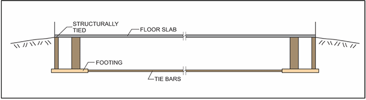
MEA, a UES Company, was selected to evaluate and recommend the most effective means to mitigate subsidence damage to the proposed DNR building in Springfield, Illinois. Based on a site investigation and subsequent analysis of the results, it was determined that the best solution would be combining foundation resistant features to the building with deep mine grouting. By doing this, the area of grouting was reduced to half the necessary volume, resulting in a savings of $1.5 million dollars. Grouting costs were further reduced by positioning the building over and adjacent to an expected lower excavation area. MEA worked with the structural engineers for the project to develop an appropriate foundation design for the project. A conceptual sketch showing the adopted design is given in Figure 1.
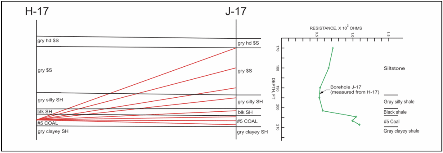
To provide a cost-effective grouting plan, detailed drilling and borehole camera work were done in order to adequately identify the range of mine void conditions. The grouting of the 220 ft. deep mine was found to present a unique problem. Based on the exploration results the mine contained extensive piles of loose fallen roof debris on the mine floor up to 30 ft. high. These piles of roof debris consisted of large rock slabs to rock which had deteriorated to a soil consistency. Needless to say, this loose and softened debris—containing very coarse to fine particles—could not be relied upon to provide any overburden support. In other words, merely filling the more accessible mine voids with grout would not provide any support against mine collapse. By combining primary, secondary, and then tertiary grouting procedures with the use of appropriate grout mixes and the specified high grout pressures, the required grouted condition was achieved. This resulted in squeeze and compaction of the rubble while also maximizing penetration. The specified (low-shrink) low strength grouts had a wide range of flowability, ranging from efflux flow rate of 30 to 40 seconds to a 4-inch slump. A Type D set retarder additive was also specified. Performance specs were used in order to allow the contractor to design their own mixes and provide the most economic in-place grout costs. The mix used was determined in the field on a hole to hole basis using previous grouting results, void-rubble conditions from drilling, MEA borehole camera results, and on the grouting state (i.e. perimeter or infill grouting and if primary, secondary, or tertiary injection). Hole to hole grout flow was monitored by measuring changes in electrical resistance at mine level. Grout return has a distinct electrical resistance. Grout detection in open drill holes allowed these holes to be water flushed prior to the grout setting up and eliminated redrilling of those holes. Also a meter was manufactured to conveniently measure the cross-hole resistivity. Using these measurements, an indication of the presence of solid coal, grouted rubble, or an open mine void could be obtained (see Figure 2).
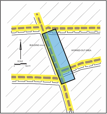
Probably the most important feature of this crosshole work is the ability to assess solid coal between the holes especially in older mines. Even if available, older mine maps typically do not show the proper pillar locations. Note on this project only main haulways are shown (see Figure 3). With cross-hole solid coal measurements unnecessary, injection holes can be eliminated and more confidence can be obtained in the layout of pillars and consequently in the grouting results. Overall the grouting beneath the building was first carried out on the perimeter followed by infill grouting. A total of 328 grout holes were drilled over 200 feet deep. This was about 20% less than anticipated. The project took 14,940 cy of grout which is close to the estimated quantity of 14,760 cy despite having incomplete mining geometries and having to account for the significant amount of rubble in the mine.
PDF Download: Foundation Treatment with Deep Mining Grouting