
100%(3)100% found this document useful (3 votes)
1K views32 pagesShopNotes Magazine 27
Trabajos en madera
Uploaded by
pepgoteCopyright
© © All Rights Reserved
We take content rights seriously. If you suspect this is your content, claim it here.
Available Formats
Download as PDF or read online on Scribd
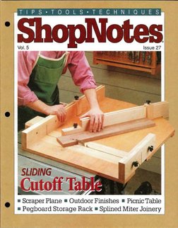
= Scraper Plane = Outdoor Finishes ® Picnic Table
= Pegboard Storage Rack ® Splined Miter Joinery
Issue 27 May 1996
rumen Donald B. Peochike
‘ern Tim Robertson,
assocurceoron Phil Totten
‘commmnurineeorons Vingcnt Ancona
David Sone
sreinscron Cary Ciiatenson
sewontuvernarone Kurt Schultz
Roger Reiland
Mati Histon
Coentiee rector Tad Kali Bre. Eire
Dong Hoke» Projet Daspn Dir: Ken
Dade» Se Proj. Dna Kent Wel = Shop
Manager Save Curtin Sop Coma: Stove
“otra +S Photographer? Crayola Engiand +
Buc Comen. Card Gordon Gales Ane,
Grephie'Dasy Dir: Satie Rider » Sew
‘Grephie Derigue Ca Glows Grophe De
ger Coat. Cor
Cireatioe Dstor Susan Du Bale Asistont
{ise De Toy DawallsSberption Managers
Sandy Haun, Pige Hopare saat Su pe
‘ue roel Nessun fp: Ren A Buca,
VP Pinning Pre Sen Maarty + Contr
lo: Rahn tatchinsn = Sr et Lara Tha
o"aapes Holly Laces » Prod Dies George
‘Chmlra Prof. Mor Carl Quijanos Bs.
Pack: Doles N. Liter » Prt. doa
‘Sayder™ Nes Adin Al Bares” Prof Deve,
[De Soy Monts» Ain, Att Cheryl
Le, Ja Fish « Recs Jeane Jean ©
Bly, Mao Ken Gti
Op Din Bib Raker st Dr Cia Sergi +
‘Meteiis Moe: Mar Mattes Cat Sort p=
“etalon «Warsow Super: Nate Seon
‘Buyer Lina Jon» Sytem Op. Tammy Av
1 Tom autor Rela Crom» Teck Supp
David Stone «Cut. Ser. Rep denier Mar
phy. Joy Rem, Sern Kena, Ana Cox, Ada
Besi. Kral Andres, Margo Pest» Ware
sonar Gna Shean, Chock Carin, Shia
(Carey, Late Pine, Sos Gia, Cth Stina
im oes
Seep fl ina tae ie A
‘Sierponn Sle uy 440. yt
=e Se
Saas sir
CORR ka
Cutoffs
't doesn't take much detective work
to identify the scraper I use in the
shop. It’s the one with the rusty thumb-
prints imprinted on the blade. While
the rust is just part of living ina humid
area, the thumbprints tell a much dif-
ferent story.
‘They're-a visual reminder of the eon-
stant (and tiring) hand pressure ittakes
to keep the seraper flexed when
smoothing a surface, Not to mention
the heat that builds up that ean make it
downright uncomfort-
able to hold.
SOLUTION. That's
why I was excited
when Ken (our de-
sign director) showed
ime the seraper plane
hhe was working on for
this issue. It holds a
seraper at a constant
angle and flexes the
blade at the samo
time. So T ean make thin, wispy shav-
ings with a lot less effort. And I don't
leave any fingerprints on the scraper.
SMALL PIECES, Because the seraper
plane is built up from pieces that are
quite small (see photo), one of the chal-
lenges isto find a safe and accurate way
tocut them. So even ifyou don't plan on
building the plane, it's worth taking a
look at the article on page 4 to cheek out
the tool setups and jigs we used to work
‘with the smnall pieces.
LARGE PIECES, Cutting lange pieces
also presents its share of problems —
especially on the table saw. For exam-
pile, think back to the last time you used
a miter gauge to erosseut a wide panel.
What probably happened is you had
to pull the miter gauge so far back in
frontof the saw that the head no longer
supported the workpiece. Or maybe the
end of the runner came clear out of the
ShopNotes
slot, Hither way, it makes it impossible
to get an accurate cut,
CUTOFF TABLE. This is where a slid-
ing cutoff table like the one shown on
page 16 comes in handy. Basically, it's
>big platform that works like a huge mi:
ter gauge. But what's different is you
can make extremely accurate crosseuts
‘on panels up to a Tull 24" wide,
Besides its extralarge capacity,
there were several othor things on my
‘wish list as the sliding table was in the
design stage. Like
having a fixed fence
(for 90° cuts) and an
adjustable fence for
making angled euts.
A stop block for mak-
ing repeat cuts accu-
rately. A replaceable
insert to reduce
chipout, And a...
ANTICIPATION.
Okay, Tl stop there.
‘The point is Took forward to each new
project like the first balmy days of
spring after a long winter. And it
doesn't always have to be a woodwork-
ing project.
ACHANGE. Recently, I've picked up
the responsibilities of Editor here at
ShopNotes, Although the job is new,
T've been around SkopNotes since Issue
No. 1,80 I feel right at home.
‘And T'm as excited about the upeom-
ingissues as when I first came onboard.
As always, well eontinne to feature the
practical tips and techniques, unique
project ideas, and unbiased tool re-
views that you've come to expect,
Inthe meantime, don't be a stranger.
Stop hy for a visit. Drop me a line (or
photo) about the latest project you're
working on, Or send along a tip that
you'd like to see published. T look for-
‘ward to hearing from you,
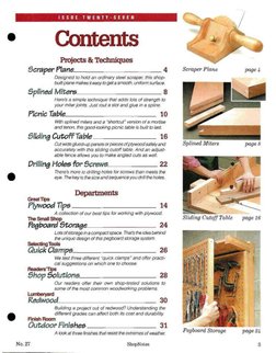
e Contents
Projects & Techniques
Scraper Plane Scraper Plane
Designed to hold an ordinary steel! scraper, this shop-
built plane makes it easy to get a smooth, uniform surface.
Splined Mitere________________8&
Here's @ simple technique that adds lots of strength to
your miter joints, Just rout a slot and glue in @ spline.
Picnic Table 10
With splined miters and a “shortcut” version of a mortise
and tenon, this good/‘eaking picnic table is but fo ast.
Sliding Cutoff Table ______________ 16
Cut wide giued-up panels or pieces of plywood safely and Splined Miters pages
accurately with this sliding cutoff table, And an adjust-
able fence allows you to make angled cuts as well
Drilling Holes for Screws. +32
There's more to driting holes for screws than meets the
@ eye. The keyis the size and sequence you dil he holes.
Departments
Great Tips
Plywood Tips _____________ 14
A collection of our best tips for working with plywood.
Sliding Cutoff Table page 16
‘The Small Shop
Fegboard Storage 24
Lots of storage ina compact space. That's the idea behind
the unique design of this pegboard storage system.
Selecting Tools
Quick Clamps_____________ 26
We test three different “quick clamps" and offer practi-
cal suggestions on which one to choose.
Readers’
Shop Solutions 28
Our readers otter their own shop-tested solutions to
some of the most commen woodworking pr
Redwood
Building a project out of redwood? Understanding the
e ditterent grades can affect both its cost and durability.
Finish Room
Outdoor Finishes _________ 31
A look at three finishes that resist the extremes of weather,
Pegboard Storage page
No. 27 ‘ShopNotes 3
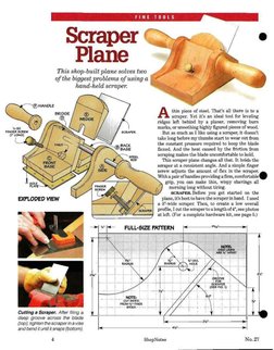
This shop-built plane solves two
of the biggest problems of using a
hand-held scraper.
Cutting a Scraper. Atter fling a
deep groove across the blade
(top), tighten the scraper ina vise
and bend it until it snaps (bottom).
4
thin piece of steel. That's all there ia to a
seraper. Yet it's an ideal tool for leveling
ridges left behind by a planer, removing burn
‘marks, or smoothing highly figured pieces of wood.
But as much as I like using a seraper, it doesn't
take long before my thumbs start to wear out from
the constant pressure required to keep the blade
flexed. And the heat eaused by the friction from
seraping makes the blade uncomfortable to hold.
‘This seraper plane changes all that, It holds the
seraper at a consistent angle. And a simple finger
serew adjusts the amount of flex in the seraper.
‘With a pair ofhandles providing a firm, comfortable
grip, you can make thin, wispy shavings all
) “morning long without tiring.
SCRAPER Before you get started on the
ne, it's best to have the scraper in hand, Tused
a B'-wide seraper. Then, to create a low overall
profile, I cut the scraper to a length of 4", see photos
at left. (For a complete hardware kit, see page 5.)
[= FULL-SIZE PATTERN, ">
‘ShopNotes No.27
ie
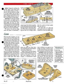
FINE
‘stpes. began by making the
Jeurved sides of the plane from
two Ve"-thick blanks, see Fig. 1
and the full-size pattern on page
4. (T used maple, but it also a
‘00d chance toexperiment witha
piece of highly figured wood, re-
fer to the photos on back page.)
‘GROVES. To hold the scraper
in the plane, an angled groove
(Kerf) is cut on the inside face of
each blank, see Fig. 1b. Note:
You'llneed tomove themiter gauge
tothe oppositeslotand rotatethe _carpet-taped the blanks together hole for a steel rod that's added
head to the opposite angle to cut sothekerfsmateh up and.attached later, see Fig. 1a
the groove in the second blank. thepaperpatternwithsprayadhe- All that's left. is to take the
‘To ensure the grooves align sive, Then, after cutting and sand- sides apart and rout a stight (14")
when the plane is assembled, I ing the sides (A) to shape, drill a roundover on the top edges only.
Core
With the sides complete, you ean
start on the core of the plane. It's
made up of two base pieces that
form the bottom of the plane, and
@& bridge that supports the han- x
dies and holds the sides together, IZ e
see Exploded View on page 4. s ‘a ONS ECE oF
BLANK. Since these pieces are ——_+
fairly small, it'ssafest toeutthem pieces are ghied up. Note: Save _ hole is drilled at an angle in the | Hardware
fromonelong blank,see drawing. theremaining partofthe blankto bridge, see Figs. 2 and 2a. Note: | "“@TAMATS |
‘The beveled end on the back use for the wedge later ‘A pair of cleats keeps the bridge | + (y y4°r me
base (B) will keep shavings from —‘ENUT. ThereSonelast thing to from sliding as you drill the hole, | * (4x7 Krued
clogging the plane. And cutting a do before assembling the core.Ty _ ASSEMBLY. After epoxying the
ingle bevel to separate the front accept a T-nut and thumbscrew T-nut in place (Fig, 2b), it's just a
base (C) from the bridge (D) en- that work together to flex the matter of gluing up the sides and
sures a tight joint when these seraper, a counterbored shank core pieces. The front base and
bridge are glued together first,
see drawing below. Then this as-
sembly and tho back base are
sandwiched between the sides,
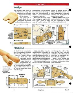
Wedge
‘The scraper is held tightly in
place by a wood wedge that
slips down into the open-
ing between the bridge
and the seraper.
‘The wedge (E) is
made from the re-
‘maining part of the blank
‘used to cut the core pieces, see
\
ee
drawing below. A eurved noteh in
the bottom allows the wedge to
slide over the thumbscrew, (1
drilled a hole and removed the
waste with a hand saw.)
5G. To hold the wedge safely
when cutting the augle on the
face, I used a simple fig. It's a
serap of “two by” material with
dowels for handles, see Fig.
Fitting the blank between two
cleats that are glued in place and.
serewing it to the jig makes it
easy to cut the wedge.
CURVED TOP. Now it's just a
matter of cutting the curve at the
top with @ bandsaw (or sabre
saw) and sanding it smooth,
3 owe
Handles
All that's left to complete’ the
body of the plane is to add a pair
of handles (F), see drawing.
There are a couple of ways to
go about this. One
ready-made. solution
that we used for the
maple plane is to
cut the handles off a
wood towel holder, see margin.
Or you can turn the handles to
shape on a lathe which is what we
did with the walnut plane shown
onthe back page.
STEEL ROD. Hither way, the
handles are held in place with an
ordinary steel rod that I picked
‘upat the local hardware store. To
strengthen the handles, the rod
passes through both sides and the
bridge of the plane, see detail ‘a’
‘This requires drilling holes for
the rod in the ends of each handle
NOTE: nar
sora
and through the body of the
plane, see Figs.4and5. To do this,
drill halfway through from both
sides using the holes drilled ear~
lier in the sides as guides.
EPOXY. After drilling the
holes, simply attach the handles
to the rod and the sides of the
plane with epoxy.
Gee
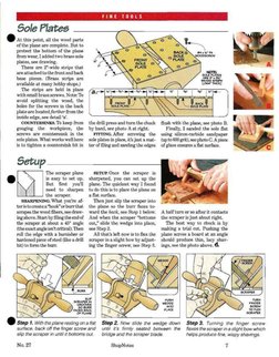
Sole Plates
At this point, all the wood parts
of the plane are complete. But to
protect the bottom of the plane
from wear, Ladded two brass sole
plates, see drawing.
‘These are 2"-wide strips that
are attached to the front and back
base pieces. (Brass strips are
available at many hobby shops.)
‘The strips are held in place
‘with small brass serews. Note: To
avoid splitting the wood, the
holes for the serews in the back
plate are located farther from the
inside edge, see detail ‘a.
COUNTERSINKS. To keep from
gouging the workpiece, the
serews are countersunk in the
sole plates. What works well here
{s to tighten a countersink bit in
‘The scraper plane
is easy to set up.
But first you'll
need to sharpen
the scraper,
SHARPENING, What you're af
teristocreatea"hook” orburr that
serapes the wood fibers, see draw-
ing above. Startby filing the end of
the scraper at about a 45° angle
(the exact angleisn't critical). Then
roll the edge with a burnisher or
hanlened piece of steel (ike a drill
bit) to form the bur:
the drill press and turn the chuck flush with the plane, see photo B.
by hand, see photo A at right.
FITTING. After screwing the using silicon-earbide sandpaper
sole plates in place, its just a mat- (upto 600;
ter of filing and sanding the edges of glass ensures a flat surface.
SETUP.Onee the scraper is
sharpened, you can set up the
plane. The quickest way I found
to do this is to place the plane on
aflat surface,
‘Then just slip the seraper into
the plane so the burr faces to-
lly, I sanded the sole flat
grit), see photo C. A piece
ward the back, see Step 1 below. A half turn or so after it contacts
‘And when the scraper “bottoms the scraper is just about right,
cout" slide the wedge into place, ‘The best vay to check is by
see Step 2, making a trial eut. Pushing the
‘All that's left now is to flex the plane across a board at an angle
scraper in a slight bow by adjust- should produee thin, lucy shav-
ing the finger screw, see Step 8. ings, see the photo above, &
2
Step 1. With the plane resting on a fiat Step 2. Now slide the wedge down Step 3. Turning the finger screw
surface, back off the finger screw and until its firmly seated between the flexes the scraperina slight bow which
slip the scraper in until itbottoms out. bridge and the scraper blade.
No. 27
‘ShopNotes
helps produce fine, wispy shavings
7
®
Assiot cutter bit
makes quick work
of routing a groove
fora spline. And
different size bear-
ings fet you adjust
the depth of cut
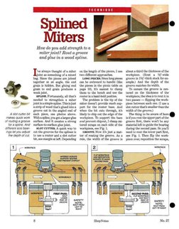
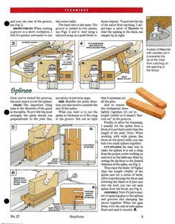
fe always thought of a miter
joint as something of a mixed
bag. Since the pieces are joined
together at an angle, the end
grain is hidden, But gluing end
grain to end grain produces a
weak joint.
SPLINE, Fortunately, all that's
needed to strengthen a miter
Jointisa simple spline. Thisisjust
astrip of wood that's giued into a
groove cut in the angled end of
each piece, see photos above.
With aspline, you get alarger glue
surface, And it creates a strong
surface-to-surface glue joint.
SLOT CUTTER. A quick way to
cut the grooves for the splines is
to use a router and a slot cutter
bit, see margin at left, Depending
Splined
Miters
How do you add strength toa
miter joint? Rout a groove
and glue in a wood spline.
on the length of the pieces, I use about a third the thickness of the
‘two different approaches. workpiece. (Rout a \s'-wide
‘LONG PIECES. Since long pices groove in 1¥'-thiek stock for ex-
can be awkward to handle (like ample.) And the depth of the
the pieces in the picnic table on groove matches its width.
page 10), it's easiest to clamp To ensure the groove is cen-
them to the bench and use the tered on the thickness of the
router in a hand-held position, workpiece, the idea is to rout it in
‘The problem is the tip of the two passes — flipping the work-
titer doesn't provide much sup- piece between each one. (I use a
port for the router base, And slot eutter that’s smaller thanthe
when the bit cuts through, it's width of the groove.)
likely to chip out the edge of the The thing to be aware of. here @
‘workpiece. To support the base isifyourout the upper part ofthe
‘and prevent chipaut, I clamp mi- groove first, there won't be any
tered scraps on each side of the material left to guide the bearing
workpiece, see Fig. 1. during the second pass. So you'll
GROOVE. Now it’s just a mat- need Lo rout the lower part first,
ter of routing the groove, As a see Fig. 1. Then flip the work-
rule, the width of the groove is piece over, reposition the scraps,
ShopNotes No.2
aL
land rout the rest of the groove, the router table. duces chipout. To prevent the tip
see Fig. 2. ‘The basic dea is the same, The of the miter from eatehing, T eat
SHORT PIECES. When routing groove is routed in two passes, pet-tape a piece of Masonite to
fa groove ina short workpiece, I see Figs. 3 and 4. And using a close the opening in the fence, soe
find it's quicker and easier to use mitered serap asa push block re- margin tip at right.
A piece of Masonite
with notches cut in
it prevents the
tip ofthe miter
‘rom catching on
the opening in
the fence,
Once you've routed the grooves, see photo on previous page. that it equeezes out
thenext step istocut the splines, SIZE. Besides the grain direc- all the glue.
GRAIN. The important thing ticn,youalsoneed toconsiderthe And to ensure
here is the direction of the grain size of the spline. the workpieces draw
in the spline. To provide the most. What. you want is to cut the tightly together, it’s cut to
strength, the grain should run spline to thickness so it fits sug length (width) so it doesn’t “bot-
perpendicular to the joint line, in the groove. But not so tight tom out” in the grooves.
Finally, to allow for trimming,
I usually cut the spline from a
block of wood thats zoider than the
length of the joint. Note: When
working with wide pieces like
those on the picnic table, you can
butt twvo small splines together,
CUT SPLINES. An easy way to
make the splines is to use a scrap
from the project you're working on
and cut it on the table saw. Start by
setting the rip fence to the desired
thickness ofthe spline, see Fig. 5.
Then raise the blade Ys"higher
6b than the length (width) of the
} spline and cut a series of kerfs.
rerostron 5 After repositioning the fence and
Erne mo (SS lowering the blade so it just cuts
‘AY into the kerf, you ean cut each
os spline from the block, see Fig.
mesmo ‘ASSEMBLY. Now it's just a mat-
ina), |) ter of applying glue to the splines
e and grooves. and clamping the
Pica pieces together. When the glue
dries, trim the end of each spline
Saw aeave flush and sand it smooth.
No. 27 ‘ShopNotes, 9
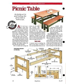
RELATED PROJECT
Picnic Table
As sturdy as it is
good looking, this
picnic table is
built to last.
Sey JN ii to0% was 0
Ss J few warm days
toremind me ofthe pienic
table and benches I'd been
planning to build, What I had in
mind was a simple, straightfor-
ward design. Something I could
knock out in a few days, yet
sturdy enough to last for years.
‘To make the table and benches
easy to build, the joinery on each
oneisidentical. Strongmortise and
tenon Joints keep the hases from
racking. And splined miters en-
sure that the tops stay flat.
‘But no matter how strong the
ar eNO
USsteew ASSEMBLY
10
Joints are, the table
‘and benches _ still
need protection from
the weather. So I used
redwood for the tabletop and
benchtops and applied an outdoor
cil. And I built the bases with less
expensive Douglas fir and ap-
plied several coats of paint. (For
‘more on redwood and outdoor fin-
ishes, see pages 20 and 31.)
‘TABLE BASE
1 started work by building the
base of the table. It consists of
two end assemblies that are con-
‘ShopNotes
nected with
stretchersat the topand
bottom, see drawing be-
low. And a pair of sup-
ports for the tap span the
upper stretchers,
END ASSEMBLIES. Each end
assembly is made up of a pair of
logs held together with a rail at
the top and hottom, see Fig. 1.
‘To simplify the mortise and
tenon joinery, each leg is built up
from two lag pieces (AJ. Cutting
‘dado near the middle and a rab-
het at the top of each piece will
form “mortises” for the rals when
No.27
RELATED PROJECT
Be.
(PRU INTERBORED SHAN HOME
(OP fROM BOTTOM BEFORE OUING
(eee rics)
“LEG PIECE
the legs are glued up.
RAILS. Each leg is held to-
gether with a narrow top rail (B)
and a wide bottom rail (C). Ten-
‘ong are eut on the end of each rail
to fit the mortises, see Figs. 1a
and Ib. And to aecept thestreteh-
ers, there are two shallow dadoes
in the top rail and a single dado
‘entered on the bottom rail,
To make assembly easier, two
counterbored shank holes are
drilled on each dado, see detail ‘a’
‘on page 10. And counterbored
shank holes drilled trom the bot
tom of the rails will be used to
attach the top, see Figs. 1 and 6.
Now it’s just amatter of gluing
upeach end assembly. To provide
plenty of working time (and pro-
tect against moisture), I used
slow-curing epoxy.
‘STRETCHERS. Tb hold the end
assemblies together, I added a
bottom (D) and two top stretchers
(&).Mfter euttinga pair of notches
ineach topstreteher to accept the
supports (added next), the
stretchers can be attached to the
end assemblies with lag serews.
TOP SUPPORTS. All that's left
to complete the base is to add
No, 27
two top supports (F). To provide
some extra knee room when sit-
ting down to a meal, the ends of
these supports are chamfered,
‘sce detail ‘b’ on page 10. Then the
supports are simply screwed in
place so the ends are flush with
the leg assemblies.
‘The bases for the twobenches are
built the same way as the table
base. But the size and number of
parts is just a bit different,
‘The biggest difference is the
leg pieces (G) are shorter, see Fig.
1. And unlike the table base, the
rails (H) that join the legs to-
gether are both the same width.
Another difference is the end
assemblies are held together
with two stretchers (1) instead of
three, see drawing below. And
both stretchers are the same
width. Here again, two notches
accept the top supports (J),
‘An easy way to
make one fong
pipe clamp is to
| thread the ends of
two shorter clamps
into a coupler.
(Eee ee
Guwees,
}
er crane
‘With the bases complete, you can
turn your attention to the table-
top. It consists ofa mitered frame
that surrounds several wood
planks, see Fig. 2
FRAME, The frame is made up
oftwoend (K) and two side pieces
(L) that are mitered at a 45° an-
fle, see Fig. 2. To strengthen the
miter joints, they're held to-
gether with wood splines. ‘These
splines fit in grooves that are
routed in the end of each frame
piece. (For more on making
splined miters, refer tothearticle
‘on page 8.)
In addition to the grooves for
the splines, you'll need to rout
two other grooves of the same
size."To accept the tongues on the
planks that are cut next, there's end pieces, see Fig; 2a.
groove inthe inside edge ofeach HAMPER. While I was at it, T
end piece, see Fig. 2. routed a decorative chamfer
PLANKS, With the frame com- (Yjo") around the top and bottom
plete, the next step is to cut the edgesofthe planks and the inside
planks (M) to length, see Fig. 2. edges of the frame pieces.
Rabbeting the end of each plank SPLINES. Before assemblingthe
on the top and bottom forms a tabletop, you'll need to make
tongue thatfitsthegroovesinthe the splines. I found it easiest to
‘Assembly. The first step is to epoxy two comers of the center of each tongue and slide the planks into the end of
frame. Clamping a spacer to the end of the frame and the frame, see middle drawing. Finally, with shims creating
positioning another clamp across the sides keeps the cor- an even gap between the planks, clamp the opposite end
ners square, see drawing at felt. Then apply epoxy to the of the frame in place, see margin and drawing at right
12
ShopNotes No.2
use the cutoffs from the top for
this. But since these pieces are
too narrow to span the length of
the joint line, you'll need to butt
two small splines together, see
Fig. 3.
ASSEMBLY. Now you're ready
to assemble the tabletop. Even
after dry assembling and check-
‘ing the fit, gluing up a large pro-
Ject like this ean be a challenge.
So I assembled it in stages, see
bottom of page 12.
‘There are a couple of things to
watch for here. To avoid filling
the grooves that the planks fit,
into, the splines are set back from
the inside corner, see Fig. 3a. And
to allow for wood movement, T
used shims to create a uniform
(4e" gap between the planks and
applied epoxy to the center of
each tongue only,
After trimming the splines
@ Assembly
‘At this point, all that’s left is to
attach the top ofthe table and the
benchtops to their bases,
‘TABLE. The easiest way to po-
sition the tabletop is to place it
upside down on the floor and cen-
ter the base on top oft, see Fig. 5.
After drilling counterbored
shank holes in the stretchers (E)
and countersunk shank holes in
the top supports (F), the top is
simply screwed in place, see de-
tails in Fig. 5. Installing serews
in the holes drilied earlier in the
top rails (B) secures the ends of
the frame,
‘BENCHES. Now it’s just a mat-
ter of attaching the two
bbenehtops. They're serewed to
the bases using the same basic
procedure as before, see Fig. 6.
CHAMEER. Thore's one last
thing to do, To prevent the legs
@ 20m plintering when moving
the table and benches, I sanded a
slight chamfer on the bottom
edges, see Figs. 5 and 6. &
No. 27
RELATED PROJECT
flush, there's just one more thing
todo. That's to “break” the sharp
edges on the top and bottom of
the table by routing 4" chamfer.
BENCHTOPS
‘The two tops for the benches are
built the same way as the table-
top. They're just smaller
While the end pieces (N) on the
denchtops are quite a bit shorter
than the ones on the tabletop, the
side pieces (O) are exactly the
same length, see Fig 4.
‘Here again, the mitered frame
for each benchtop is held to-
gether with splines, And a
tongue on the end of a single
plank (P) fits into a groove in
each end piece.
-#
Co
GreatPlywood Tips ¢
Here's a collection of tips that are
sure to come in handy the newt time
you're working with plywood.
Cutting Guide
‘mClamping a board to plywood exactly where you want can be a encethat indicates the path ofthe
ides the base ofa circular saw guessing game, To solve this, blade (or bit). So to ensure an
fr router 80 you can make a use acutting guide,see photos, accurate ent, just align one of the
straight cut, But positioningit on ‘The wayit works simple."The edges of the guide with the layout
the workpiece so the ent is made edges of the guide act as arefer- lines on the workpiece.
‘There's nothing complicated
about making the eutting guide.
Start out with an extra-wide base
made from ¥thick hardboard,
see drawing. After gluing and
serewing a plywood fence to the
base, one reference edge is cre-
ated by trimming off the waste
witha cireularsaw. Andthe other
SSS | bycuttingit offwithastraightbit
‘onsscao sase—m] ) | in a router e@
nore. “| ‘To use the guide, clump it toa
Taw sawoerourer | workpiace so the edge aligns with
en Gores Se thelayout marks. Then just make
a cut with the same blade or bit
that you used to create the refer-
tence edge. Note: Since a router
bit may not be exactly centered
inthe base of the router, keep the
same point on the hase against
the fence.
A Laying a sheet of foam insula ‘A By cutting an extra deep rab-
tion on the floor makes it easy 10 wicod, simply postion C-clamps bet, you can cenlera sorewon the
ccut.a full sheet of plywood down along the edge and use a wedge thickness of the workpiece. This
to manageable size. to apply pressure. way, it won't split out the side.
4 ShopNotes No.27
‘Few things are more frustrat-
ing than having a saw blade chip
cut the face veneer on an expen-
sive piece of plywood.
While a blade that’s specially
designed to cut plywood can pre-
vent this (see box at right), you
can also get good results with a
combination saw blade.
‘SCORE. One way Is to use the
saw blade to lightly score the ply-
wood, see Fig. 1, To do this, raise
the saw blade so it just barely
cuts through the face veneer and
make a pass,
‘This way, the blade severs the
‘wood fibers of the veneer instead
e Reducing Chipout_____|
of tearing them out, A second
full-depth pass completes the cut
and produces a crisp edge.
INSERT. Another way to get &
‘quality cut is to replace the origi-
‘nal metal insert on the table saw
withazero-clearance insert made
of wood, see Fig. 2
The basic idea here is to elimi-
nate the opening between the
blade and the insert by providing
support right up next to the saw
blade. This way, when the blade
cuts through the workpiece, the
insert backs up the bottom face of
the plywood and prevents the ve-
neer from splintering,
OE ET CES
‘One way to improve the quality of eut when
working with plywood is to use a saw blade
that's designed just for that. purpose.
‘To produce razor sharp cuts, both the 10"
table saw blade and 714° circular saw blade
shown here have 200 small stee]teoth sot around
the perimeter of a thin, tapered rim. A thick,
center hub adds rigidty to the blade,"
Note: To avoid binding, adjust
the blade height so only the
rim (not the hub) passes
through the workpiece,
Flush Trimming
W'To create the look of a solid
‘wood panel, the lip on a piece of
edging that stands a bit proud
needs to be trimmed flush with
the surface of the plywood,
PLANE. If there are only a few
pieces, I use a block plane to re-
‘move mast ofthe waste. To avoid
gouging the plywood, apply a
piece of masking tape and plane
until the tape starts to “fuzz,” see
Fig. 1. With the tape removed,
‘you can finish up with a sanding
block. Just sand until pencil
marks on the plywood start to
disappear, see detail.
ROUTER. A router and a flush
trim bit make quick work of the
Job if you have a lot of pieces to
trim, see Fig. 2. Clamping a serap
tothe workpiece keeps the router
from tipping. Anda rabbet in the
serap provides clearance for the
lip on the edging, see detail.
‘ShopNotes
15
Sliding Cutoff Table
Wide Panels. To make accurate crosscuts onpan- Angled Cuts. By attaching an adjustable fence
«8 up 1024" wide, this sliding cutofl table combines that pivots around the curved end of the siiaing
2 large plywood platform with a long fixed fence. table, you can make angled cuts as wel
can' tall you where its ex- easy to erosscut panels up to 24° ble has two “vero-clearance” in-
‘actly. But there'sa point of no wide, see topleft photo. And add- _serts that prevent chipout on the
return for the miter gauge on my ing an adjustable fence allows bottom of a workpiece. ‘To make
table saw. Especially when I pull you to make angled euts as well, this work for both 90° and 45° @
it back to erossent a wide panel. ee top right photo. ‘cuts, it's just a matter of remov-
It’s the point where the hes STOP BLOCKS. Whether you ing one insert and replacing it
starts to wobble because therun- make straight or angled cuts, with another, see photo B.
ner isn't fully supported in the sometimes you need x number of SAFETY. Finally, a pair of wood
miter gauge slot, And that makes pieces thatareidenticalin length, blocks (see inset photo below)
‘it almost impossible to crosseut a To ensure accuracy, a pair of stop work together to stop the table at
wide panel safely and accurately. blocks that slide in T-shaped slots the end of a cut. This “buries” the
‘That's why I built this sliding in the fencescan be lockedtightly _ blade in a thick
cutoff table. With the workpiece in place, see photo A. block on the
resting on a lange platform that INSERTS. In addition to the back of the ta-
slides across the saw table, it’s stop blocks, this sliding eutoffta- ble, see photo C,
A. Stop Blocks. A pait of stop blocks B, Inserts, Tworomoveable nserts(one C. Safety System. A thick wood block
allows you to Cut multiple pieces to for90"and the other for 45" cuts) reduce and two stops prevent the blade from
iength quickly and accurately. ‘chipout on the botiom of a workpiece. being exposed at the end of a cut
16 ShopNotes No.2
ae
‘OVERALL DIMENSIONS:
@& Pee toew raze
Soe
sath)
nscer
| Hardware
A Large Bave (1) 2tex27-9A Py. (00) te" Threaded
& Small Base (1) 22x58 -% Py, cai |
C Insert Plates (2) 6x26-% Ply. oiler Botte
D Runner (1) Yex%s-2%2 -eaeene
E Front Face (1) YexB2-16 Threaded Knbe
F Insert Blocks (4) SxB¥e-10 + aerate
G Short End Blocks (8) YaxBl2-3 Tiraadad Kobe
H Back Face (1) aeaaia es 9 Get rants
1 Long End Block (1) Ya x BV2- 25 } *
J. Top Fieces (2) Vox2-1% ies raster
k Stops (2) Yox2-3%e Woodscrews
L Fence Pieces (2) Vax Be-32 © (4) #8 x2" Fh
M Mounting Block (1) Sota ete
N Spacer (1) Wena -Yo Mas. s a
e oan) ee ‘, mie aii
P ouppore (1) axe s8 order a complete
@ Blade Guard (5) %x3%4- 52 bach ica
R Stop Blocks (2) Saxtle-4 Se eee Sok ee
No. 27 ‘ShopNotes 7
To builel accuracy mf
into the siiding
table, check that
the corner of the
large base piece
Js square, and the
miter gauge stot
is parallel to
the blade.
To installa
threaded insert,
chuck a cutoft bolt
with two nuts tight-
ened against each
other in the dlril
press, Then turn
the chuck by handl
FEATURE PROJECT
T began work on the cutoff table
by building a plywood base. Tt
serves as a platform that carries
the workpiece through the blade.
‘The base is made up of three
parts: a large (A) and small base
(B) piece with a removeable in-
sert plate (C) sandwiched in be-
tween, see Fig. 1. Note: To make
straight and beveled cuts, Tmade
two insert plates.
CURVE. To keep the adjustable
fenee (added later on) from bind-
ing, there's a curve cut on the
outside comer of the large base
piece, see Fig. 2. This requires
establishing a pivot point for the
fence, then cutting the curved
shape and sanding it smooth.
RUNNER.The base is guided
bya hardwood runner that slides
fa
in the miter gauge slot. To pro-
duce aceurate cuts you'll need to
‘make sure this slot is parallel to
the blade.
‘The runner fits in a dado eut in
the bottom of the base. When lay-
{ng out the location of this dado,
the idea is to have the blade cut
through the center of the insert.
‘Todo this, place the base piece on
the saw table 3° away (half the
‘width of the insert) from the cen-
ter of the blade, see Fig. 2a. Then
mark the location of the dado by
using the slot as a reference.
Before cutting the dado, it's
best to have the runner (D) in
hand. It’s a piece of hardwood
(maple) eut to fit the miter gauge
slot s0 it slides amoothly without
any “play”, see Fig. 2b.
‘THREADED INSERT. After cut-
ting the dado and screwing the
runner in place, all that's left is to
install athreaded insert, see Fig.
3 and margin at left. It fits in a
hole that's drilled at the pivot
point for the adjustable fence,
2
18
ShopNotes
ae)
Fixed Fence & Support Rail
‘The base is held together with
two parts, A fixed fence runs
across the back edge and sup-
ports the workpieee as you make
a cut, see Fig. 4. And a support
rail adds rigidity to the front.
POCKET. To slip the inserts in
‘and out of the sliding table, the
fence and support rail each have
“pocket” that's built up from%4"-
thick hardwood blocks (maple
‘To form this pocket in the sup-
port rail, a front face (B) is cut to
length, see Fig. 6, Then an insert
block (F) is sandwiched between
two short end blocks (G),
Except for its size, the fence
isn't all that different. But here,
there's a long back face (H). And
another insert block (F) fits be-
tween the short end block (G) and
along end block ().
‘TSLOT. Before assembling all
these pieces, a T-shaped slot is
cut in the fence for a toilet bolt
that Jets you adjust the stop block
{added later). Making this slot is
simple, First, cut a shallow
‘groove in the back face (FD and a
deeper groove in the long end
block (1), see Fig. 5a. Then rabbet
the top edge of the longend block.
ASSEMBLY.T) assemble the
fence and support rail, the end
blocks only are glued in place. (L
used the insert blocksas spacers.)
When the glue dries, the fence
is screwed (not glued) to the hase
pieces so it's square to the blade
and flush with the back edge. And
the support rail is serewed flush
with the front edge.
INSERTS. At this point, the in-
sert: plates (B) and insert blocks
(F) can be serewed together to
form the inserts, see margin
‘They're held in piace with knobs
that tighten into threaded in-
serts, see Pigs. 4 and 5,
STOPBLOCK. All that's left is
to add a stop block. It consists of
atop piece (J) and stop (K) glued
up in an L-shape, see Fig. 6.
‘Tightening a knob on a toilet bolt
that passes through the top piece
holds the stop block in place.
5
With two inserts, you
‘can use one for 90°
cuts (lop) and the
‘other for 45° cuts
(bottom).
Adjustable Fence
At this point, the cut
off table can be used
for making 90° cuts.
But to make angled
cuts as well, T added
fan adjustable fence
with a simple clamp
that locks it in place,
seo Fig. 7 and photo.
TSLOT. Like the
fixed fence, a T-slot
for astop block runsalong the top
edge of the adjustable fence. Af-
ter cutting two %4"thick fence
pieces (L) to size, this T-slot is
made the same way as the one in
the fixed fence, see Figs, Sand Sa,
‘NOTCH. Once the fence is glued
uup, a noteh is cut at one end. To
providea pivot point that lets you
swing the fence to the desired
angle, a knob passes through a
hole drilled in the notch and into
the threaded insert installed ear-
lier, see Fig. 7a. Tightening (or
Toosening) the knob lets you at-
tach (or remove) the fence.
‘CLAMP. Now you can add the
lamp. Tt consists of three parts:
a mounting block and arm made
of hardwood, and a Masonite
spacer in between, see Fig. 7b,
‘What makes this clamp workis
the mounting block is thinner
than the base, This way, the
7| seae TOP Lock
SEER et eB
Me
o
wien
posusras.e
rence
nese
mec Ra.
é i
a. b. mone
=e \
Fe
}
J
Bee =
Tags >
oe ee = /
Dancin
ermoren) e
spacer ereates a small gap that
allows the arm to pinch against
the base of the cutoff table when
‘you tighten the lamp.
To provide this clamping pres-
sure, the mounting block (31) and
spacer (N) are first glued in
place, see Fig. 9. After installing
threaded insert in the mounting
block and attaching the erm (O)
‘with serews,a simple knob ean be
used to tighten the clamp, see
Fig. 7b,
Finally, it's just a matter of add-
ing'a second stop block for the ad-
Justable fence, see Fig. 7,
ShopNotes:
No.27
Stop System
‘Al that’s left to complete the slid-
ing table is to add the stop system.
Besides supporting the sliding ta-
ble, it covers the exposed part of
the blade that passes through the
fixed fence at the end of a cut.
‘To make this work, the stop
system consists of three parts: a
support, a blade guard, and a pair
of stop blocks, see Figs. 10, 11,
and photo Con page 16.
‘SUPPORT. The siepport (P) is &
long strip of wood that attaches
to the extension wing of the table
saw, see Fig. 10. It prevents the
sliding table from tipping at the
‘beginning and end of a cut.
‘To determine the length of the
support, simply measure the
dopth of the saw table and add
12". This gives you 6" of support
at each end.) After cutting the
support to length, it's just a mat-
ter of bolting it flush with the top
of the saw table, see Fig. 10,
BLADE GUARD. Now you can
add the blade guard (Q), see Fig.
11. It's a thick block that's made
by gluing up five pieces of 34'-
thick hardwood. In use, the part
of the blacle that cuts through the
back of the fence is “buried” in
this block at the end of a cut.
Before attaching the guard, 1
cut Yyr-wide chamfers on all the
outside edges. Then the blade
‘guard is glued in place so it’s cen-
tered behind the insert,
‘STOP BLOCKS. The last thing
todoistoadd two stop blocks (A).
‘These blocks prevent the blade
from catting through the blade
guard by creating a positive stop
at the end of a cut. One block is
‘glued and serewed to the end of
the support, see Fig. 10. The
other attaches to the bottom of
the cutoff table, see Fig. 12.
‘To determine the location of
this block, position the cutoff ta-
ble on the saw so the front of the
fence is centered over the saw
arbor, see Side View. Then giue
and serew it in place. Note: An
Us" gap between the block and
support keeps the table from
binding, see End View. #&
12 NOTE Revove nsec >
SAWBLADE TO SEE ARBOR
No. 27
‘ShopNotes
IN THE SHOP
etter
Jn the surface, assembling a
roject with screws is
fairly straightforward, Just drill
a hole (or a series of holes) and
drive in the serews.
Maybe that's why
ittsso frustrating when
things don't go exactly
as planned, For exam-
ple, the serew doesn't
raw the pieces tightly
together. Or the head
ofthe serew snaps off,
If something like
‘that happens, it’s only
natural to blame the serew. But
more than likely, thereal problem
‘ean be traced back to the holes
that were drilled for the serews.
‘So when working with stand-
‘ard tapered woodserews, I drill a
series of stair-stepped holes to fit
tthe shape of the serew as closely
as possible, This can either be
done with individual deil bits. Or
you can use a special combination
bit, sce right-hand box on page 23.
‘TWO HOLES. Toensureasmooth
assembly and a joint that's held
tightly together, I start by drill-
ing two holes, A large siank hole
‘goes all the way through the top
piece, see photo above and draw-
ing in margin, And a small pilot
hole stopsin the base piece. Note:
‘To drill these holes as accurately
as possible, I use brad point bits.
SHANK HOLE. The shank hole
provides clearance for the
‘smooth part of the screw. And it
keeps the threads in the top piece
from “catching” and creating a
2
gap between the pieces, see Fig. 1. the pilot hole ix to prevent. the
SIZE. Aneasy way toselect the wood from splitting.
right size drill bit for the shank To do this effectively, the pilot
hole is to hold the serew in front hole has to be sized correctly. If
ofthe bit, see Fig.2a. Thesidesof it'stoolarge, the holding power of
the bit should just barely stick the serew is reduced. Too small
out pasttheshank.’Thenwhen you and it inereases the chances of
drill the hole, the screw will slide splitting the wood or snapping
through without binding, see Fig.2. the head off the screw.
PILOT HOLE. The next step is As a rule, I drill the pilot hole
to drill the pilot hole in the base slightly smaller than the root of
piece. The most important job of the screw (the part of the screw
ShopNotes No.27
@ write the shank hole and pilot
NTH
botwoen the threads). This gives [4
the threads something to grab, |")
Countess ort CENTERS
ROE ON SHANE ROLE
‘Here again, to find the correct
size drill bit, line up the bit with
the screw. But this time, place the
serew behind the bit, see Fig. a.
‘The root of the screw should just,
peek past the sides of the bit,
=
morno
i=
i
DEPTH. Another thing to keep
jn mind is the depth of the pilot
hole. This will vary depending on
whether you're working with
hardwood or softwood,
Since hardwood is more likely
to split, [drill the hole almost as
deep as the screw will penetrate,
cet
see Fig. 3. Leaving two or three
threads to bite into the wood is
plenty to produce a solid grip.
But with softwood, 1 drill a
shallower hole — usually about
half the length of the threaded
part ofthe serew that will bein the
base piece,
APPEARANCE
down tight.
hole take care of the basic me-
chanies of a serew joint, you also
pearance of the serew head.
projects, I drill a countersink
‘This leaves the screw head ex-
TCLS Ue LSS
There's a big difference in these two counter-
sink bits. One uses a single cutting edge that
slices the wood fibers and leaves a clean hole,
see left-hand photo. ‘The other has multiple
utters that serape the wood and produce a
scalloped cut, see right-hand photo.
‘The important thing is to drill
the countersink after the shank
hole and pilot hole, see Fig. 4.
‘This way, the tapered sides of the
bit automatically center it on the
shank hole. (For more on coun-
need to consider the finished ap-_tersink bits, see box below left.)
COUNTERBORE. Fora finished
‘COUNTERSINK. On most shop appearance, a counterbore lets
‘you recess the verew head below
the surface, This is a deep,
posed and set slightly below the straight-sided hole that's drilled
surface. The beveled sides of the
countersink match the shape of
the screw head so it can draw counterbore is drilled before the
to accept a wood plug or filler.
‘The thing to be aware of is the
sshankchole and pilot hole, see Fig.
5, (Ifyou drill the shank hole first,
the bit will wander because there's
no centerpoint to guide it.)
'So which bit do you use to drill
1 counterbore? Since a twist bit
also forms a countersink at the
base of the hole, it's « good choice
for flathead woodscrews, see Fig.
6. But for a roundhead screw
that's at on the bottom, 1 use a
brad point bit. &
TEC
Ityou're installing alot of screws, thistapered
combination bit saves time by drilling a series
of holes in a single operation, You can use it to
Grill the countersink, shank hole, and pilot
hole, see left-hand photo. Or adjust it to drill
the counterbore as Well, see right-hand photo,
¢ J
|
ShopNotes 23
To set the screw
head just below
the surface, oil
the countersink
deep enough so
the head fits the
top of the opening,
Sources
“*Wooderat (single
mutiple cutee cour
‘ersink, com bite)
200226:163
* Garrett Wade (com
‘ination bis)
200-221-2942
1 Woodworker Supply
(ingle cutter cour
torink, comb i)
200-648-0292
* Conscantines (mut
{ipl cutter counter
‘toh, comb ie)
(200-225-8087
Just open the
doors to find
the hidden
storage space
inside this
compact rack.
ree
t first glance, it’s hard to
ine that you can or-
‘anize a wall full of tools in this
compact storage rack, see photo.
But a closer look reveals the “hid-
den” storage space inside.
This extra storage is provided
by two doors that have pegboard
‘onboth the frontand the back. To
provide easy access to tools on
‘each side, the doors swing out in
opposite directions, refer to the
photos on the back page.
FRAME, The doors are sup-
ported by a sturdy frame made
from “two-by” material (I used
Douglas fir) and a %4"-thiek ply-
wood top and bottom, see draw-
ing below left. It’s held together
with simple (yet strong)
lap joints that are madeby ~~
cutting a series of notches
{in the frame pieces.
A pair of stretchers (A)
used to attach the rack to
the wall are rabbeted on
each end, see Pig. 1. These
rabbets fit dadoes in the
back of the two uprights
(B). Another pair of dacloes on the
inside face accept short. arms (C)
that are rabbeted on one end.
Before assembling the frame,
it’s easiest to drill a hole in each
‘arm for a pin that will allow the
doors to pivot, see Pig. 2. And a
shallow groove is cut for the top
‘and bottom that are added later.
ASSEMBLY. Now you can as-
semble the frame. The stretch-
ers, uprights, and arms are held
together with glue and screws,
‘To add rigidity to the frame,
the plywood top and bottom (D)
are cutto fit between the grooves
in the arms. But before gluing
and serewing them in place, 1@
moaemens °
‘added hardwood trim strips ()
‘to cover the front edges.
With the frame complete, you can
add the doors. They're just sim-
ple wood frames with pegboard
‘on each aide, see Fig. 3.
‘The overall height of the doors
is the same. But the back door is
1" narrower so it swings past the
front door when you open it, see
Fig. 84.
Determining the length of the
frame pieces is easy. The stiles (F)
‘oneach door are identical in length.
(To provide an 14" clearance at the
top and bottom, T cut them 36"
long.) But the front rails (G) are
1" longer than the back rails (H).
(This takes into account the over
all width of the doors and the,join-
‘ety that holds them together.)
With the frame pieces cut to
length, matching rabbets are cut
on both sides for the pegboard
panels, see Fig, a. And anotch in
the ends of the stiles accepts the
rails, see Fig. 3b,
PANELS. After screwing the
frame pieces together, its Just a
matter of entting front (1) and back
door pamels (J) to fitand screwing
them in place, see Pig. 3c. And a
serap pull (K) is glued to the
front of the back door. door, see Fig. 4. and 4a. ‘These place, a hole is drilled in each up-
ATTACH DOORS. All that's left bolts pass through holes in the perarm fora spring loaded catch,
isto attach the doors. They pivot arms (drilled earlier) and thread see Fig. 5. Note: One catch
‘on two hex bolts that pass into into 'Enuts in the inside face of mounts to the baek of the front
bronze bushings installed in the the arms. door. And the other'ison the front,
top and bottom edges of each Finally, to lock the doors in of the back door, refer to Fig. 3. Hardware
(2) 89 14 P he
© (20) 70129" Fine
© (0) 20x14" Pauw
(60) 0 2) Pe
© (a) 42 HecBolee
© AW Fue Washes
1 (6) Fender Washoe
Strout
8 eyes enp
Brose Bushings
# (2) Letetond Spr
rad
SELECTING TOOLS
Quick Clamps —
: Inere’s one thing that's al-
Prices ays in short supply when
clamping up a project — a third
wove hand. With one hand positioning
fe'camp: $12.95 | the clamp, and the other keeping
22" clamp. p38 | the parts aligned, an extra hand
2" camp 918-95 | to tighten the clamp would speed
Quick-Grip_ | things up considerably,
ene: sabe ‘That's where these quick
olan clamps come in, see photos below
Sorcame gosee | and prices in margin. They free
| ia up one hand by allowing you to
Pillck- Star | position the clamp and apply
Quic!
(American Tool)
800-767-6297
pressure with the other hand.
But there's more to @ clamp
than how handy itis to use. Tosee
how they performed when gluing
up a project or making @ tool
setup, we ran the clampsthrough a
series of tests, see photos above.
To provide a range of view-
points, we asked three wood-
workers with different amounts
of experience to test the clamps:
Cary (a weekend woodworker),
Steve an advanced woodworker),
Gar meas
and Ken (a professional earpen-
ter and cabinetmaker).
BB These clamps look quite differ-
‘ent from each other: Do they work
differently too?
Steve: The two clamps that are
the most alike are the E-Z Hold
and Quick-Grip. With these, I
Just squeeze the handle to slide
the lower jaw along the bar until
it's tight against the workpiece.
Ken: While both clamps use a
pumping action to advance the
Jaw, [liked the in-line handle on
the E-Z Hold the best. (See the
top drawing at left.) That's be-
cause no matter how the clamp is
oriented, it's convenient to use.
But since the pistol grip on the
Quick-Grip is perpendicular to
the bar, it ean be awkward to use
depending on the position of the
clamp. (See enter drawing.)
Cary: The Quick-Star tises a
different approach altogether.
‘The lower jaw on this clamp is
spring-loaded, 30. it advances
“automatically” like a tape meas-
ure, (See bottom drawing.)
Bi How does that work?
Cary: It's pretty simple really,
Pulling the lower jaw down the
bar applies tension to the spring.
And releasing it retracts the
spring and pulls the jaw against,
the workpiece.
Once the jaw is snug, it works
like. standard bar clamp. As you
No.27
tighten the handle, a screw ap-
plies the clamping pressure.
Which is why the Quick-Star ap-
plies more pressure than the other
two clamps. (See drawing and
photo above right)
‘Ken: But that's not to say you
can't get a tight fitting glue joint
with the E-Z Hold and Quick-
Grip. Since they don’t produce as.
much clamping pressure, the key
@ is tomake sure the joine fits tight
before gluing the pieces together,
‘And since I do that anyway (even
Clamp Pads. The large jaws
and the soft rubbery clamp pads
on the E-Z Hold (left) and Quick-
Irregular Shapes. Unlike the Quick-Grip (left), the
clamp pads on the Quick-Star (center) and E-Z Hold
(ight) make full contact with iregular-shaped objects.
when using heavy-duty clamps),
that’s not a big deal.
BE What about the clamp heads?
Cary: That's one of the biggest
differences I noticed. Because
both clamp heads on the Quick-
Grip are fixed, the pads don't
make full contact when I campan
irregularshaped object. (See
photo above left.)
Bat the lower clamp head on
the Quick-Star is basically just. a
ball and socket joint. So the head
Grip (center) provide a more sta-
bie grip than the smaller plastic
pads on the Quick-Star (right)
Clampi
Pressure.
pivots as I tighten
the clamp and the pads conform
to the shape of the object.
Steve: While it doesn’t have
quite as much flexibility, the up-
per clamp head on the E~Z Hold
also pivots.
In fact, the whole upper jaw
slides off the bar so I can use it as
a spreader, That's handy when
need to take a project apart after
dry assembling it to check the fit,
(See margin.)
WOne last question. Besides the
color, are there any real differ-
ences between the clamp pads?
Steve: Size is one thing. The
large pads on the E- Hold and
Quick-Grip seemed to distribute
pressure farther along the joint
line than the small pads on the
Quick-Star; (See photos at left.)
Cary: And I liked the positive
grip provided by the soft, rub-
bery pads on both the B-Z Hold
and Quick-Grip.
Cary: Choosing the best quick
clamp was a tug of war.
liked the spring-loaded jaw
and the extra clamping pressure
‘you get with the Quick-Star. But
not enough to pay over $20 for it,
So I pieked the E-Z Hold in-
stead. It only costs about half as
much, And it would easily handle
most of my clamping needs.
No.27
Recommendations
Steve: At first, it was the low cost
of the E-Z Hold clamps that
‘aught my eye too. (Especially if
‘you're buying a bunch of elamps.)
Butthe real reason I picked the
E-Z Hold was the convenience of
the in-line handle. Also, convert-
ing the clamp to a spreader is
‘something that would come in
handy for me once in awhile,
ShopNotes
Ken: I guess that makes three of
us, Although it doesn’t produce
as much clamping pressure, T
chose the E-Z Hold too.
It exerts plenty of pressure if
you start with a tight-fitting
joint. And the large clamping sur-
face provided by the soft, rab-
ery pads distributes pressure
evenly along the joint line. &
27
Pressure. With a
pressure gauge
‘mounted ona
hydraulic cylinder,
we measured how
much pressure each
clamp applied.
4
_ =
Simply reversing
the jaws on the
E-Z Hold clamp
allows you to use
itasa spreader,
[ire ma Lk eas
ShopSolutions °
A
Like many woodworkers, Tuse
a shop-made “sled” to rip a
‘straight edge on rough cut lum-
ber, But rather than buy special
clamps to hold boards securely to the base of the sled, see drawing. and glued sandpaper to the base.
the sled, a pair of spring-loaded And the other fastens toa board —_Andastop ghied and serewed to
hinges applies all the pressure I that acts as a hold-down, the end of the base helps push the
need, see photo. ‘To hold the workpiece securely worlspiece when making a cut.
One leaf of each spring is at- in place, I screwed rubber “feet” Terry Vikla
tached to a rail that’s serewed toto the bottom of the hold-down Cottage Grove, Minnesota
Brad & Nail “Drill Bit”
| Predrilling a pilot hole for a [_ _
‘brad or finish nail helps prevent | Bead'on wat
them from splitting the wood. | SANSEUsD
But Idon'talways have drill bit | terre
that's the same size as the brad or
finish nail,
‘Todrill holes that are the exact
size, I cut the head from one of the
‘brads ornails I'musing and chuck
‘the shank in my drill. The shank
works like a drill bit to drill a hole
that fits the brad or nail perfectly.
David Krimmel
San Diego, California
28 ShopNotes No, 27
emake
Quick Tips
A Since his lip balm is always
hanay. Bill Johnson of Akron,
Ohio, applies it to screw threads
lomake the screws easy to drive.
Finishing Easel
=n
To make it less tiring on my
back when finishing doors and
other flat projects, I built an
“easel” that holds the workpiece
‘ata comfortable height, see photo.
‘The main parts of the easel are
apair of uprights made from “two
by” material that are set up on a
sawhorse, see drawing. A square
notch in the bottom of each up-
right fits behind a stretcher
serewed to the legs of the saw-
horse, see detail 'b’. And an an-
gled notch in the back edge
determines the slope of the easel.
‘To keep the uprights from tip-
pping, I drilled two holes in each
one for a pair of long dowels. By
gining and serewing one end of
No. 27
4A To increase the grip of his push
block, John French of San Di-
go, California, glues shalt liner
10 the bottom of the block.
each dowel to the same upright,
‘you an slide the other one on the
‘dowels to adjust the easel for pro-
jects of different widths.
Finally, a dowel in the front edge
ofeach upright supports the work
piece. And a piece of PVC pipe
that’s cut in half Cengthwise) and
serewed to the uprights keeps the
wet finish on the project from
sticking to the easel, see detail ‘x’
‘Allan Gabel
Sussex, Wisconsin
‘ShopNotes
> Right out =
of the pack. (=
age, t'seasy \
to identiy the <<)
grit on a hook and
loop. sanding disk.
Butif'you change disks fre-
quently, the grit markings on
‘Back soon wear ott
‘So Wayne Loper of Duncar-
nan, Pennsyivania, uses a per-
‘manent marker to label the griton
the one place on the front of the
disk that doesn't clog or wear
out — the center of the disk
If you'd like to share your original
solutions to problems you've faced,
send them to; ShopNotes, Attn: Shop
Solutions, 2200 Grand Avenue, Des
Moines, 1A 50312. (Or if it's easier,
FAX them to us at: 515-282-6741)
‘We'll pay up to $200 depending on
the published length, Please include
a daytime phone number so we can
call you if we have any questions,
Redwood
T=: 8 good reason why the houses my
grandfather built still have their original wood
siding. The siding is made from redwood.
‘And even though the finish on many of those
homes has deteriorated over the years, the red-
‘wood is still as solid as the day he nailed it in place.
‘That's because redwood has a natural resistance to
both insects and decay.
Because of this durability, redwood is an ideal
wood for a project that’s going to sit outside (ike
the pienic table on page 10). But to take advantage
of its ability to fend off damaging inseets and rot,
you'll need to take a close Jook at the different
ides of redwood.
‘TWO GROUPS. Although there are a number of
different grades, each one falls into one of two main
‘groups; Heartwood or Sapwood.
‘When buying redwood for an outdoor project, I
make ita point to select Heartwood lumber, Heart-
Wood is easy to identify by its reddish-brown color,
see photos at right. But there's
something about. it that’s even
more important than eo
‘The heartwood is ent from the
inner part of a redwood log —the
part that makes it resistant to
insects and decay. But there's no
natural resistance inthesapwood Color. Unlike the creamy colored
that's cut from the outer part of sapwood (top), the red heart-
wood resists insects and decay.
the log.
HEARTWOOD.'The two best
gpades of Heartwood are Clear All Heart (straight
grain, free of knots) and Heart ‘B" (some irregular
grain and a few small, tight knots), see photos be-
low. Note: We used Heart ‘B on the picnic table,
Not surprisingly, these two grades of redwood
are also the most expensive. Here in Des Moines,
Clear All Heart costs about $4.40 a board foot, and
Heart ‘B' is $3.50 a board foot,
Aless expensive graile you may want to consider
for some projects is Construction Heart/Deck
Clear All Heart, Lumber with this grade is
siraight-grained and free of knots.
Heart ‘8’. You'll see some irregular grain
‘and small knots in Heart ‘B' lumber.
Construction Heart/Deck Heart. Look for
knots of varying sizes with this grade
30 ShopNotes
Heart ($1.50 a board foot), see bottom photo. Al-
though boards in this grade aren't as straight
grained and have langer knots, you can sometimes
cut around them.
WORKABILITY. Regardless of the grade you use,
there area few things you should keep in mind when
‘working with redwood lumber. Like most other
softwoods, redwood cuts easily.
But to help reduce splintering,
it's still a good idea to first drill
pilot holes before nailing oF
serewing itn place.
‘And if there are any small
splinters along the edges, glue
them in place before sanding or
finishing as they havea tendency
to “eatch” on sandpaper, paint-
brushes, and rags,
Also, when routing redwood, it's best to sneak up
on the profile by making a number of passes to
reduce tearout and splintering.
AVAILABILITY. Becatuse redwood is such a spe-
cialty use item, you're not likely to come across it at
your local home improvement center. But you ean
find it (or order it) at many lumberyards.
If you have trouble locating redwood, you can
give the California Redwood Association a call (15-
382-0662) for the nearest dealer in your area. @
Lia)
* Outdoor Finishes
ether it's drenched in the rain or baked by
the sun, the finish on a piece of outdoor
furniture has an incredibly tough job. So it's impor-
tant to select a finish that protects the wood from.
damage caused by extremes of weather.
Inaddition, there are a couple other things I look
at before choosing an outdoor finish. How it affects
the appearance of the project for instance. And the
‘maintenance required to preserve the finish,
To strike a balance between all these things, I
‘usually select from three different types of outdoor
finishes: penetrating oil, spar varnish, or paint,
‘The easiest finish to apply isa penetrating oil that's
‘specially formulated for outdoor use. Wiping the oi
on and off (I apply at least three coats) seals out
‘moisture by penetrating inside the fibers of the wood.
Since the oil doesn’t build up on the surface, it
‘won't erack or peel. And it preserves the natural
look and feel of the wood, see photo A.
MAINTENANCE, But it doesn't take long before
an oil finish starts to look dull and loses its ability
to keep out moisture. So about every two or three
‘months, you'll need to wipe on a fresh coat.
For a more durable finish that still preserves the
natural beauty of the wood, I use an exterior (ma-
rine) spar varnish, see photo B. It forms a protec-
tive barrier against: moisture on the surface of the
‘wood. And its extremely resistant to wear,
‘FILTERS. When selecting a spar varnish, look for
one with ultra-violet (UV) filters. These filters ab-
sorb the UV rays from the sun that break down a
finish over time.
‘To take advantage ofthe filters, it's best to apply
at least three coats of spar varnish, But since the
filters gradually lose their effectiveness, you'll need
to establish a regular maintenance schedule,
‘The important thing is to renew the finish before
ft starts to deteriorate. About once a year, I sand
the finish lightly and apply another coat.
PAINT
QP hove tdes the wood good eat ofpaint sit
[provides the best protection against the weather.
That's because it keeps out moisture and pre-
vents sunlight, from penetrating the finish.
As with any finish, the end result is only as good
as what's underneath, So start by applying a heavy
‘coat of penetrating (outdoor) oil. Especially on end
grain that will wick up moisture if the paint fails.
PRIMER. When the oil dries completely (about
two or three days), the next step is to apply a good
quality alkyd (oil-based) primer. While it provides
excellent resistance to water, an alkyd paint ean
crack as the wood moves with changes in humidity.
‘TOP COATS. So when it's time to apply the top
coats, 1 use a more flexible latex (water-based)
paint, see photo C. Two coats will usually protect
the wood for several years or more.'
~< Penetrating Oil. Even
though it darkens the
wood, the most natural
ooking outdoor finish is a
penetrating oil. To ensure
continuous protection
against moisture, apply
another coat of o
every few months,
< Spar Varnish. With an
exterior spar varnish, you
get a more durable (and
{glossier) finish, Even so,
you'll need f0 maintain the
finish about once a year
10 prevent cracking
or peeling.
“Paint. Winilo it hicies
the natural beauty of the
wood, a painted finish
offers the best protection
against the weather. And
you don't have to worry
‘about renewing the
finish as frequently.
No.27 ‘ShopNotes 31
Scenes from the Shop
A The highly figured grain on this walnut scraper wood wedge and brass finger screw hold the seraper at
plane creates a fino tool that's as pleasing to look at as just the right angle to produce thin, wispy shavings.
itis to use, Like the scraper plane shown on page 4, a “And brass sole plates on the botiom resist wear.
‘A A panel full of tools is just part of the storage pro- other side as well as a back door concealed rwithin
vided by the pegboard rack shown above left and on (center). Swing out the back door and you can even.
‘page 24. Open the front door and there's storage on the hang tools on the other side of it or the wall (right)
You might also like
- ShopNotes #31 (Vol. 06) - Low Speed Grinding Jig100% (4)ShopNotes #31 (Vol. 06) - Low Speed Grinding Jig32 pages
- Shopnotes #51 (Vol. 09) - Band Saw Upgrade100% (4)Shopnotes #51 (Vol. 09) - Band Saw Upgrade32 pages
- ShopNotes #27 (Vol. 05) - Sliding Cutoff Table - TextNo ratings yetShopNotes #27 (Vol. 05) - Sliding Cutoff Table - Text32 pages
- ShopNotes #15 (Vol. 03) - Sliding Table PDF100% (2)ShopNotes #15 (Vol. 03) - Sliding Table PDF32 pages
- ShopNotes #66 - All New Table Saw Workstation100% (1)ShopNotes #66 - All New Table Saw Workstation38 pages
- Shopnotes #87 (Vol 15) - Router Table Sled PDF100% (2)Shopnotes #87 (Vol 15) - Router Table Sled PDF54 pages
- ShopNotes #60 (Vol. 10) - Aircompressor Caddy100% (2)ShopNotes #60 (Vol. 10) - Aircompressor Caddy34 pages
- Versatile Sawhorse & Lumber Storage Solutions0% (1)Versatile Sawhorse & Lumber Storage Solutions1 page
- ShopNotes #26 (Vol. 05) - Cordless Driver - Drills - Text100% (1)ShopNotes #26 (Vol. 05) - Cordless Driver - Drills - Text32 pages
- Crafts - Woodworking - Magazine - (Ebook) - Shopnotes #44 - Grinding Station100% (2)Crafts - Woodworking - Magazine - (Ebook) - Shopnotes #44 - Grinding Station32 pages
- ShopNotes #10 (Vol. 02) - Heavy Duty Lathe Stand - TextNo ratings yetShopNotes #10 (Vol. 02) - Heavy Duty Lathe Stand - Text32 pages
- ShopNotes #02 (Vol. 01) - Wooden Joiner's Mallet - Text100% (4)ShopNotes #02 (Vol. 01) - Wooden Joiner's Mallet - Text32 pages
- LIBRO MIT CURSO Inference From Data and Models (Atmospheric Science Open Course MIT 2005 231s) PDFNo ratings yetLIBRO MIT CURSO Inference From Data and Models (Atmospheric Science Open Course MIT 2005 231s) PDF231 pages
- (Ron Lenk) Practical Design of Power Supplies100% (8)(Ron Lenk) Practical Design of Power Supplies225 pages
- 6419A-En Configuring Managing Maintaining Windows Server08 Servers-TrainerWorkbook Vol2No ratings yet6419A-En Configuring Managing Maintaining Windows Server08 Servers-TrainerWorkbook Vol2190 pages
- Rotary Chuck System Parameters Setting Instructions - RLNo ratings yetRotary Chuck System Parameters Setting Instructions - RL1 page


