
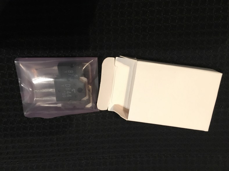
One job that I need to do whilst I am waiting for the decal of Cora to be finished (my excitement to see her is certainly building!!) is to swap out the pushbuttons on the patch PCB board. Why? Because it’s possible to do, and I want Cora to get every single upgrade to her old parts for new ones that are available, identical and still being made. I’m already preparing to replace EVERY SINGLE SCREW in her with a new one of the exact same specs and have been researching this and ordering some online in preparation (I will go through and review every screw in a JUPITER 8, what size they are and where to get them from in an upcoming post with pics…it’s a daunting job!)
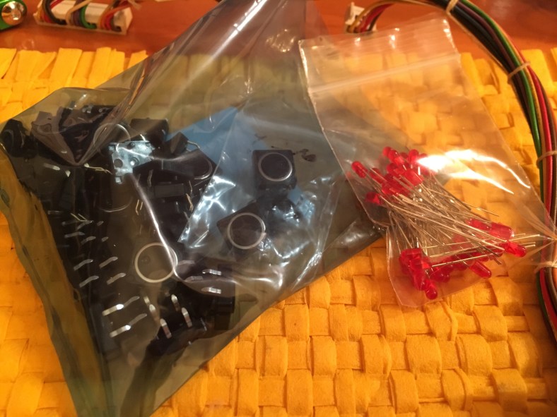
The Alps brand push buttons are still made to the exact same specs today which is a great thing. They’re not very expensive, and actually are also the identical ones that Roland used for the TR808 that they were manufacturing at the same time back in 80. But it’s important to get the identical ones that fit into the pcb holes and are the right height. I started by ordering 3 samples from Syntaur, that I know are the correct part. There are several different ones, different heights, normally on or normally off action, different little black support pin configurations etc so you need to be careful. From Syntaur they cost $2.95 each, here is their part number:
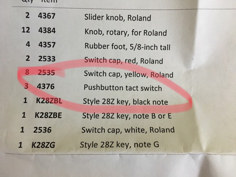
Once they arrived and I had a good look at them I came to the educated conclusion that they were the identical model Alps that are on RS Components.com .. this is their part number:

However look at the price difference. 40 buttons on Syntaur would cost you $118 .. plus their min shipping charge of $40. That’s $158 (assuming that’s all you ordered). Verses $34.88 and free shipping from RS. The same identical Alps brand button. Hmmm.
I must add here that some repair shops choose to upgrade these push buttons to an even higher spec by using more expensive push buttons that are sealed around the button to remove the chance of any dust entering the button, they often use ones by Omron. Up to you. There is a bit of fiddling to remove some of the black stem stands underneath the button to make it fit. I chose to replace with the originals as the “clicking action” would likely feel different and i want to keep everything as original as possible.
So here is what they look like:


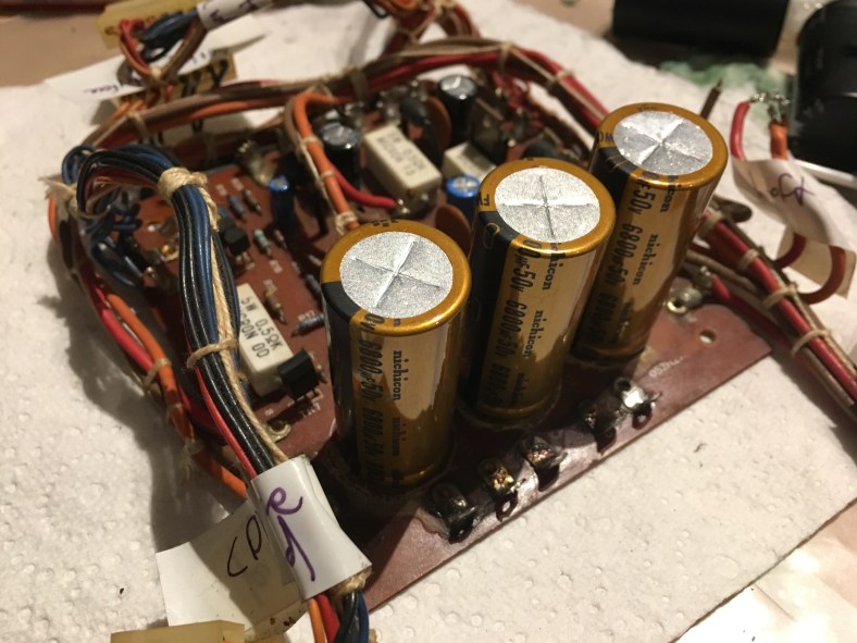
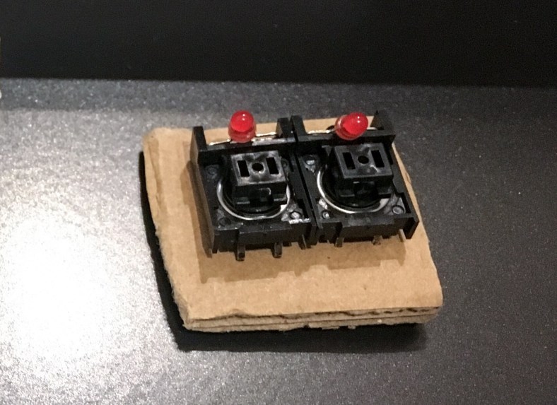
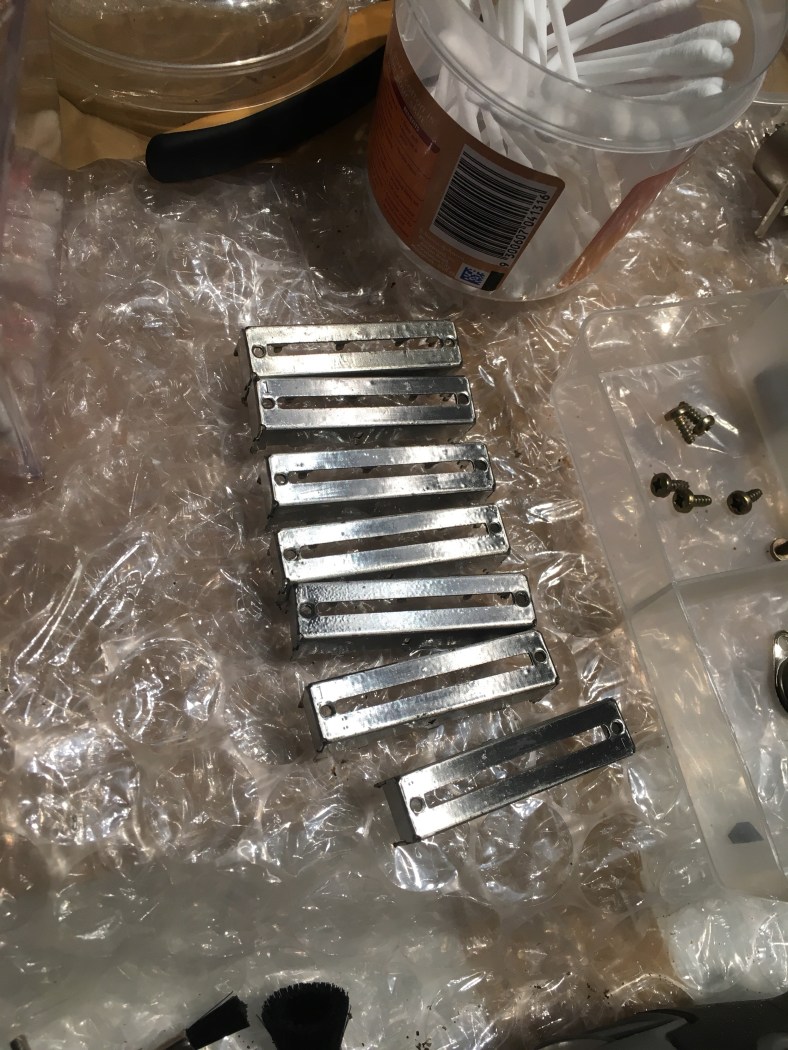
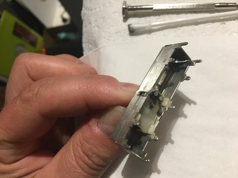
Note on the actual round button a small depression dot. Means little other than it’s nice when installing to line them all up in the same direction so it looks neat. If you push on one of the old, original pushbuttons on a Jupiter 8 and instead of making a single click, it makes a double click or a crunching sound, or if the pushbuttons are 35 years old (ie Cora) then you know that they need to be updated and replaced. Often they are still working technically, but full of dust or other contaminants and rusted inside and it’s just a matter of time before they occasionally fail (frustratingly annoying) and some pushes dont register, so you are sometimes pushing buttons twice to get them to work, or they will completely fail. Here is what the patch button board looks like when you take one out of the jupiter 8 top panel (there are 2 of them)…. it’s after I cleaned all the cigarette Ash, smoke machine gunk and dandruff from it that had accumulated!:

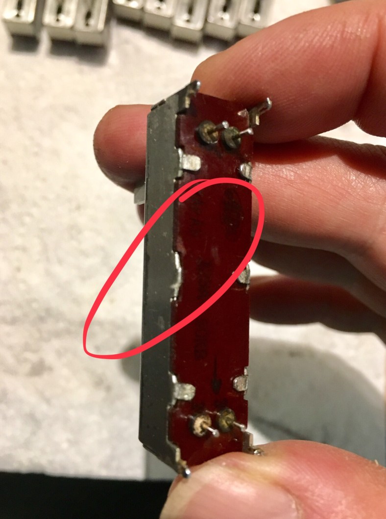
On Cora, it seems there had been attempts at repair of push buttons in the past. Whoever did it, made a real mess demonstrated by the dismal soldering job. I was saddened to see that Cora had been treated so carelessly inside. How dare anyone do this to a Jupiter 8! What was he using to solder with a clothes iron? It appears that they heated up the tracks so high that a few of the pcb pads had lifted, and the solder points looked generally “burnt”. I suspect it was a previous owner who had little idea about how to solder by the looks of it.
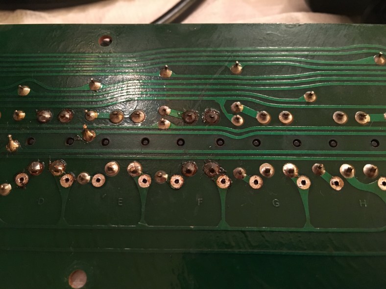
The repaired buttons were obvious from the burnt solder but also by the different shade of colored red LEDs that were re-installed. They didn’t match the original LED color of the others by a longshot, including a difference in intensity when they lit up. They were a lot lighter in overall shade when Off, and a lot brighter when on. You can see here the different shades of the LEDs, the one on the left is a lighter red:  Basically… it looks bad when in use because the lower intensity LEDs give the impression of the button being “unhealthy” when pushed and lit up. All the LEDs really need to be identical. It was time to swap out those 1982 LEDs for some new ones, and the best time to do this was whilst I was already there and swapping over the push buttons at the same time. If you’re going to do this one job you may as well do both as it will save you a lot of time and effort if you need to do just the other one later.
The first step is to remove the button caps, and there is definitely a trick to it. If you try and simply pull them upwards and off you will snap the plastic hinge that they are attached to below and then you’re in trouble, as they do not make the plastic hinge housings anymore (although they are seemingly a perfect candidate for a 3D printing trial). This is the black plastic hinge and area I am talking about:
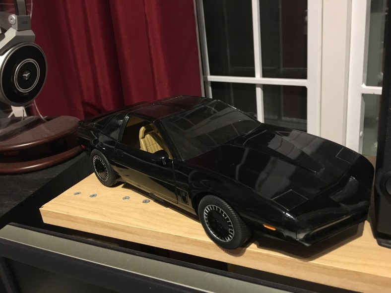
 Quite incredible that a hinge made of a piece of plastic bending back and forth was used, I mean how long did they honestly think this would last before snapping off?? I remember when I was a kid and was making my model Knight Rider Car, the parts came on a frame that needed to be twisted off and it took a few pushes back and forth and the piece was broken off! This sure looks it would behave similar. I still have the car I made when I was 13 it sits on my studio speaker shelf proudly
But I digress…
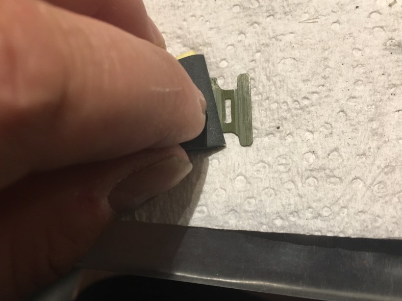
Roland sourced these black button frames from Alps also in the 80s. They were also bought by Korg and used in the Korg Monopoly and Polysix, the exact same black button frame ! (Korg just used different looking button caps on top but these guys are underneath!) If you try and twist the button cap off you can end up with the same problem..snap. Ouch. If you pull them off on the wrong angle, you can snap the little clips inside and underneath the button cap as the plastic has all gone brittle after 35 years and don’t like pressure being applied. This pic below is the underneath a button cap, with my screwdriver pointing to the clips that break off:

If the little clips snap then you’re up for another button cap. These are slightly easier to find as some colors have been remade in the past few years for TR808s, so the white, yellow orange and reds can be found but some of the colors such as the blues and the green are impossible to find. So be gentle gentle. Also the remade ones are a different white.. the original Jupiter 8 white button tops had a slight ivory color .. quite classy whereas the new remade white ones are made from a color plastic that could only be described as “ice cream container stark white”.

The left hand one is original NOS I received recently from Roland, it’s never seen the light of day (that makes them go yellow… see my previous post “Restoring white Jupiter 8 buttons..”) that’s just the slight ivory color used when they were new. Don’t think for a moment that you can just replace one button cap with the newly made ones and it will blend in next to the others! The new ones also have a different surface texture…slightly rougher. It’s obviously a different mould to the 80s originals so it’s not unexpected… the ones floating around currently come from a 3rd party called Technology Transplant, nothing to do with Roland. The new ones are fine… just not identical when next to the old. But break an old one and you’ll be up for 12 new button caps in the case of white ones, if you don’t want it to look like an obvious repair job and silly. Here is a video to show how to take the caps off successfully:
Using a very small jewel flat screwdriver you gently and patiently twist between the button cap and the plastic hinge, back and forth until it pops off. It takes some practice. Practice on the available replacement colors first! And do the blue and green last. A side note …from experience the white button caps are the most brittle and crack the easiest!
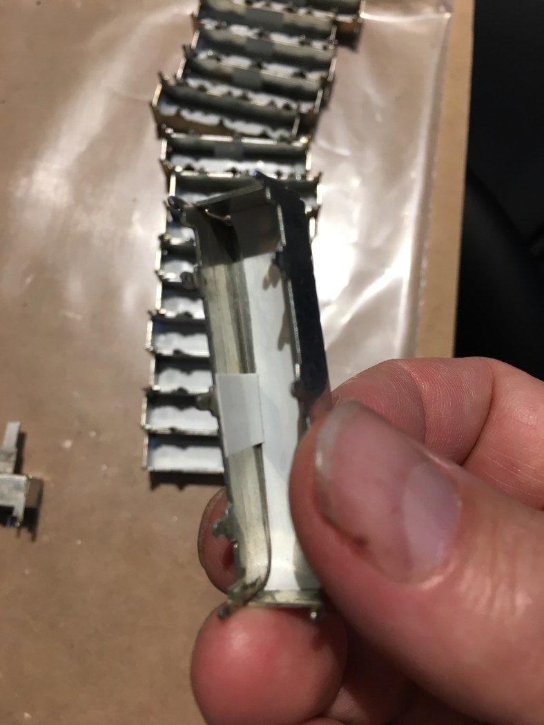
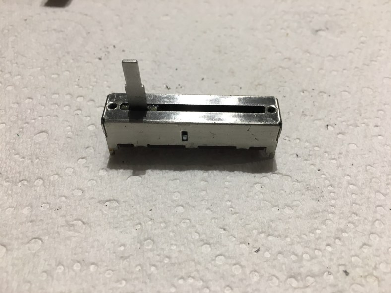
The two long patch button PC boards also bow CRITICALLY just from existing and worse if you hold them by the long ends. One fast move and the board will simply fold in half and crack as your hands clap together and that’s the end of it. Here they are performing their bowing trick just from resting on the table!!  The thickness of these boards are wayyyyy under spec once populated with all the push buttons (this situation is even WORSE for the slider PCBs). It’s quite shocking actually how flimsy it becomes. Be very careful with how you handle the boards especially as they have a long clump of leads that are hard-wired to the end of each of them that can’t be removed and dangle around on the desk getting caught on everything (my soldering iron went flying) as you flip the pcb over and over to work on it.
  Another case of setting aside plenty of time and not rushing. Enjoy the job. Do only one board a day otherwise youll get frustrated and try to rush it and that’s when damage is done.
I started by desoldering the 4 pushbutton legs and the two LED legs. You can’t get the black plastic frame off the board to get to the button without doing the LED as well.


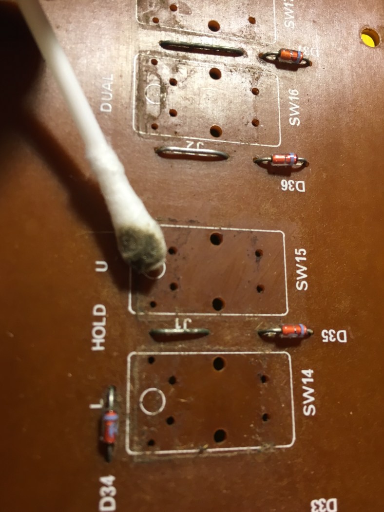
A lot of dirt and muck from years and years of abuse were trapped around and underneath those buttons as well:

I used a cotton bud soaked simply in water to clean it up:
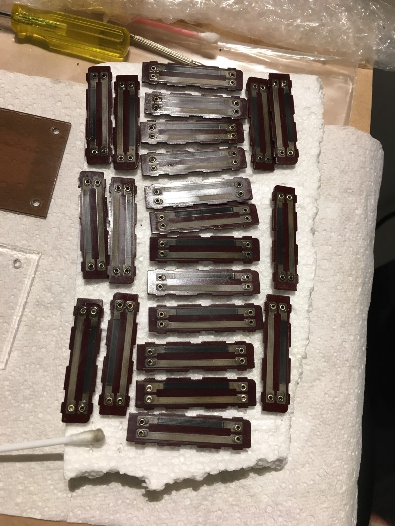
all of the buttons removed from both boards and cleaned up:
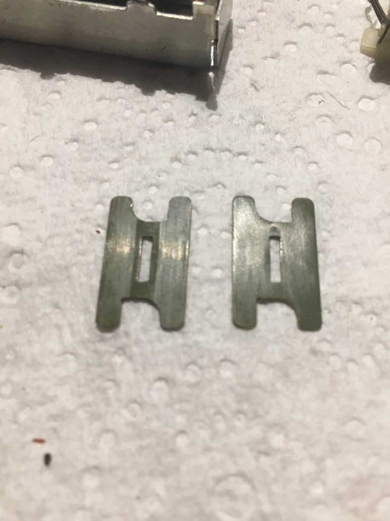
All the plastic frames need to have the LED removed from the frame and cleaned …just a cotton bud and water:

and new ones put in.

This requires a degree of skill. The legs need to be bent to fit EXACTLY back into the plastic frame holes and to sit at EXACTLY the same height in the frame. You need to get a few extra LEDs in case they break as you bend the legs. They’re cheap, only a few cents each. You need 44 (there are a few extra you’ll need for one of the Slider boards also) so get a pack of 50 x 3mm size. You could get a color other than red if you liked, such as green, it won’t look original but hey each to their own. Just don’t make the mistake of getting high intensity LEDs as they draw extra current and put extra strain on the switching chips on the boards that can burn them out. Not all LEDs are the same. Some have less of an even diffuse in the plastic, making them look kinda smokey and cheap. And some are not quite as wide as some others at the top or bottom of the bezel, although they’re technically meant to be. So buy a couple from different stores and compare how they look before purchasing 50. This is a Jupiter 8 after all…. Get the best quality ones you can find. Hell I bought 3 different sets of 50 before I settled on one that I was happy with! After all I’ll be staring into Cora’s twinkling lights with loving abandon for years to come so it has to be just right.
Also make sure whilst in the store (or when purchasing online) that all 50 come from the SAME BATCH…there are variances in brightness and the plastic they use between batches and brands … again there is not meant to be… but there is. One store pulled out a tray of “mixed” red 3mm LEDs and there were 3 different looking ones just in that tray! Stores keep receiving them from different suppliers and some spotty-faced junior assistant just chucks them in on top of the others in the tray it seems and gives the LED soup a bit of a stirr to mix them up. Shameful. Then it’s lucky dip for an unsuspecting customer.
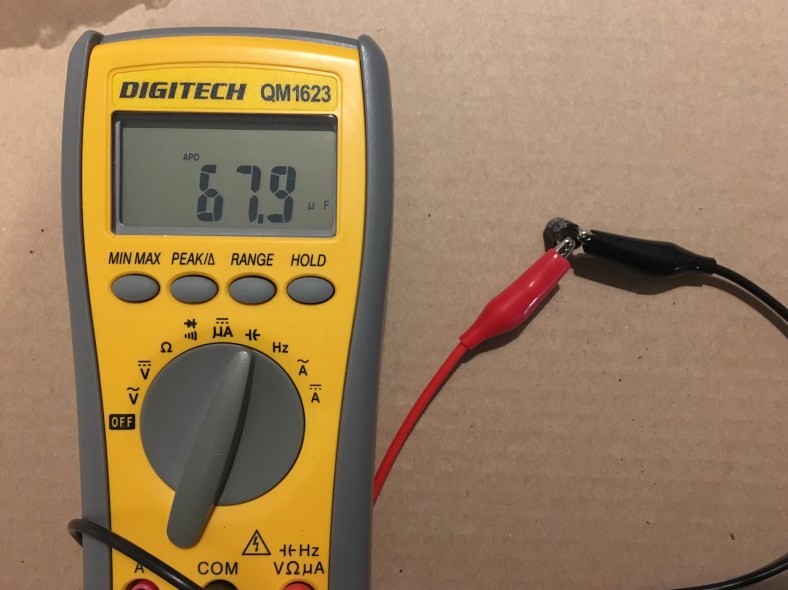
Also test every LED before soldering it in. Every so often you find one DOA. Good to check brightness as well in comparison with each other. A great testing unit is this one… it’s not expensive and you’ll use it again one day after the job:

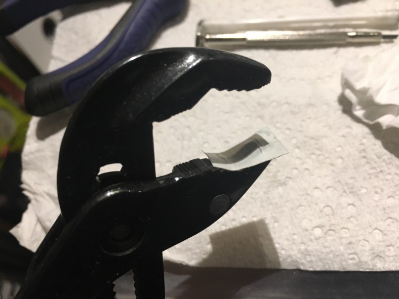
Ok so first bend the LED legs outwards sideways with your pliers:
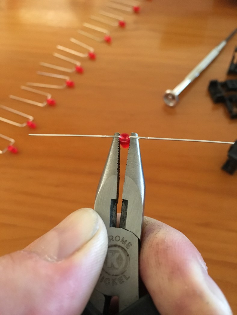
Sometimes … you will perform this first bend and shockingly a leg will just snap off or fall out of the bezel! This is another reason why you were smart and brought a bag of 50 LEDs, not the exact 44 (you did listen to me, right ??) Then after some trial and error you will find the right spot on your pliers to use as a measuring point for bending the legs over, I found that the 3rd set of teeth in from the tip of the pliers was my perfect spot:

Same for the other side … keep it lined up nice and straight now…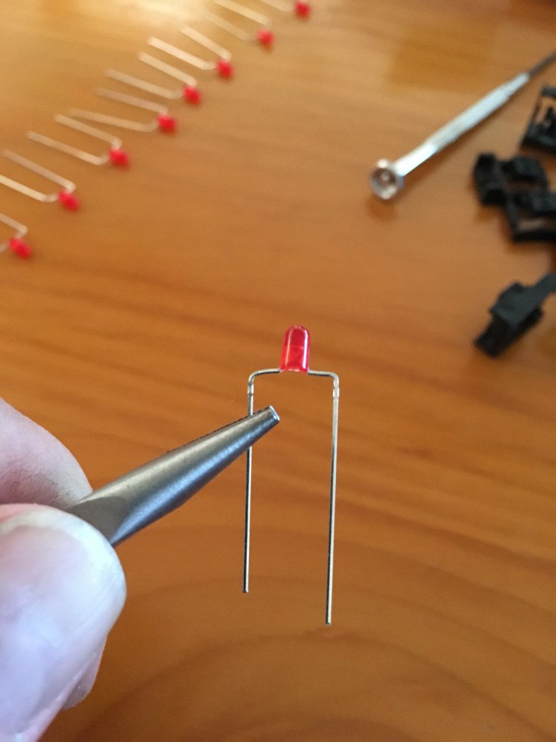
And then it drops into the button frame perfectly. Sometimes it’s not clear where the holes in the frame are for the legs… I’ve been thrown a few times thinking “daym this one is defective there’s no hole!” but I’ve always eventually found it. Patience…

Make sure you have orientated the LED the same way (ie +ve and -ve legs) as the one you just pulled out! LEDs have flat markings on the bezel body to help with this but your handy blue tester you purchased will help a lot as well. Then it’s just a matter of putting the new pushbutton into the PCB (it doesn’t matter what orientation/direction they go in but it’s nice to line up the depression dots). And then replacing the black plastic frame back over the top and making sure it’s sitting flat and the LED legs are coming thru the pcb to be soldered.
BUT… before you solder the LED in… it’s important that you get the sitting height of the LED right … and just as importantly, consistent with the others. I did this by sitting a button cap on top of the black frame (without actually clipping it in) and checking how far out the LED protruded up through it and making sure it was the same distance poking out every time: 
This bending and measuring is a slow and delicate process. I enjoyed doing it. I took the bag of bits away with me and sat beside a river in the country and did them all whist I had a line in the water. By dusk I had 2 rainbow trout (a third got away ..but that’s another story) and a bag of correctly bent LED patch frames to show for it (plus a few empty beer bottles.) And the soldering I did later back home under decent light. All of the new LEDs, frames and buttons in their place. Note the attention to making all the LED heights above the button frames all the same when looking from the side:

Lastly, i decided not to mount the button caps back on just yet. Always thinking ahead, there’s every chance that I could have a dead pushbutton or LED after soldering and until the board is in Cora and functioning and every button tested I don’t need to risk stressing those rare button caps and chance another cracking of a clip to get to a button or LED again. The button caps can sit in a bag for now, looking like brightly colored candy just dying to be eaten…


 He thought maybe he had a few complete, unused sliders in the workshop!! Finally an understanding friend! After searching for so long it was the most exciting possible news ever! Majid is a truely nice guy. We had a great chat, and a few days later he managed to locate them and sent me some pics of what he found.

 And some… simply don’t have any printing on them at all. They’re blank underneath! Like this:


 unwrapped and on the workshop bench:


 You can see here I have sanded the one on the right side down smooth. The two on the left are still to be done. Then leave it for at least another 24 hours to completely harden up.
 It was on the other side of town in an industrial area near the airport and this place was literally on the opposite side of the street from a workshop I had been in discussion with to attempt the tricky decal silk screen printing. Google maps had confused me with its directions to find the place and I thought it was the decal workshop when I walked in by accident with Cora ! The guy “Clive” that greeted me was cool and accommodating, and once I realized my mistake I quickly changed my stream of reasoning for seemingly being there and discussed powder coating hehe. He found the exact Roland powder coat color from metal swatches, he checked to see that he had the actual paint color in stock, gave me some advice on how to strip the paint properly (rather than sand blast it) and even ran out the back to grab a tin of paint thinner and said “you’ll need this for the job too before you bring her in” and handed me the tin for free! He also talked about temperature concerns of the oven due to the thin metal and how he would put it in a particular spot in the oven where it would not buckle or warp due to overheat. Right there and then, I knew this guy was the man for the job and the powder coating place I had originally in mind that had done some previous work for me (much closer to home) was to be bumped for this most precious of jobs. I never much liked the disgruntled old stir-crazy menopausal woman that begrudgingly would answer the desk at my local workshop anyways. And you never got to speak to the actual guy doing the work there so you never knew if the messages were getting through. But here, this guy Clive was …da Man. He knew his stuff. He’s been doing this all his life… he’s made all the mistakes there is to make. I resigned myself to needing to return and make several more trips across town. But nothing would be too much trouble for my special Cora, to have her handled with respect and care that she deserves… and done right.
 Every place where there was a bracket weld underneath, there was a round metal coin-like mark on the other side. It was a silver filler on the top, to hide the weld burn. And in many places, the weld was still causing a “dip” in the surface top metal. I spoke to a few people about this.. including Clive who said that the paint would collect in these small crators, and, umm, in his words “look like shit” if they were left that way. The answer he said was to tap them out from the other side. Now apparently i was a panelbeater! The number of different hats I was wearing during the course of this project was shaping up to be rediculous. But I jumped right in.
 I used the head of a nail, upside down, as suggested…with Cora on a solid wooden table. With 4 solid taps, knocked back the panel to be even and flat. Trial and error to get the weight and swing right, occasionally I overdid it and had to flip the panel over and swing it back the other way to be flat:


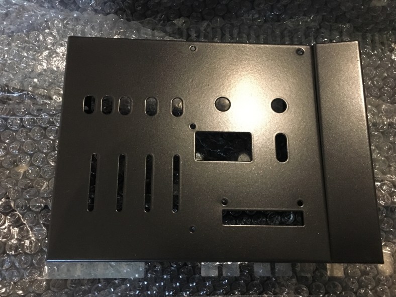
 Then it was on to the large base panel. First a stripping:


