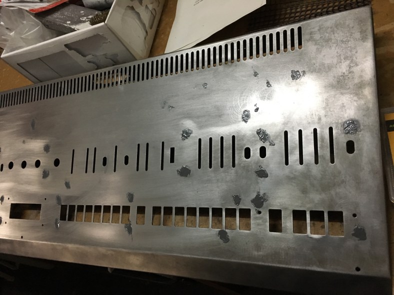
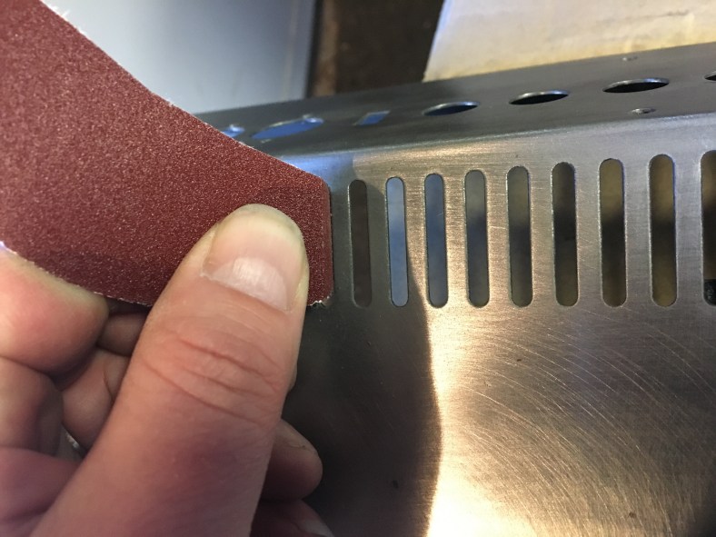
Now with Cora’s panel returned to me and finally looking beautiful after her powder-coat success, it was time to finalize the decal art file. I had tweaked and tweaked Jeff’s (from Custom Synths) original .cdr vector-based Coreldraw file for weeks in anticipation of this day. I used high- res SLR pics I had taken of her panel before I took the mighty plunge into stripping her that fateful day on the balcony some months ago. So I imported my pics into the decal session and laid the images underneath the parts to make some adjustments.
Vector based files are the only files accepted by laser cutting and decal printing workshops. And they can only be made in software such as Coreldraw and Illustrator and AutoCad. Vector based removes any chance of graininess that can occur when you zoom in on a graphic image such as a jpg or pdf because it is a point to point representation rather than pixel. In other words, if you have a line across the screen, all that a vector based file will contain is a start point measurement and end position, the thickness and the color of the line needed. Where as a JPEG graphic will require information about every single pixel position and color along the way from the start to the finish of the line. Vector based files are usually much smaller in size than their graphic equivalents. They’re a pain in the ass to create tho. It’s a whole other technique and skill required when compared to Photoshop. You can’t just scribble and paint in an area with a paintbrush. It just simply doesn’t work that way.
Jeff described how he needed to “cut up the film a few times to line things up” as part of the decal printing process. I would have no such opportunity or luxury as I was handing the job over to a workshop to do and one of the first things they stressed when they gave me the quote was “THIS is assuming the file you give us is lined up perfectly … Right?.” He emphasized that there would be no cutting or fiddling if any things were “out” and instead would only be prepared to make another set of films to fix the problem. Films run at $200 each for this job. You need a film per color. There is 2 colors on the Jupiter 8 panel (well actually there’s 3 if you count the rear Roland logo which is by itself in a cream white color). Things could blow out very fast if the films weren’t 100% perfect from the start.

Jeff suggested that I print to a clear film transparency first, on my own, and lay it over the panel to see how things lined up before the big dive into film. Transparency film is the clear plastic film they use for overhead projectors. A great suggestion however a clear film transparency of the size of Cora’s panel (over a meter long) would still run in the vicinity of $100 per print. I envisioned needing to print several times to tweak and this could still run into big bucks. Plus it was not easy to find a place that would print transparencies of that size.
Along the line as part of my investigation I had one print shop suggest that perhaps I would like to print to transfer paper instead for only a meagre $26. Yes, I would! That would be good enough to get the job done! Harder to see through but certainly more useable than printing to standard 80gsm white paper. But once I told him the size, this then became another difficulty. Nearly every print shop I contacted did not have transfer paper this wide… or long. It really needed to be one single piece or there was room for error to creep in. And a few complained about printing to transfer paper and problems of smudging as the ink tends to sit on top of transfer paper rather than soak in. Finally I found a print shop that was attached to a large university art department that said “sure… no problem.” The students used it for their large scale design projects. Perfect!!
Next problem was that printing places simply don’t print white. The rely on the fact that paper is white. They print with Red, Yellow, Blue and Black or any combination. Before printing I had to modify the file to a color. Black was no good as Cora’s panel is close to black and I would not see it as clearly. Yellow is usually a weak color when printed. I went with pure red, the strongest printing color with the most contrast against the black paint. Eventually The first transfer paper test print came back.

I overlaid it on Cora’s panel and sure enough, it was not quite right. Thank the lord I had done this step beforehand !!!

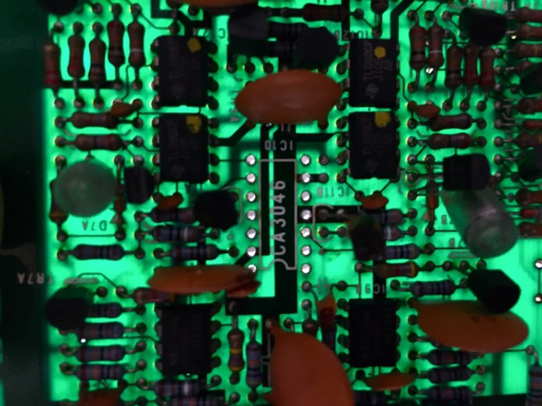
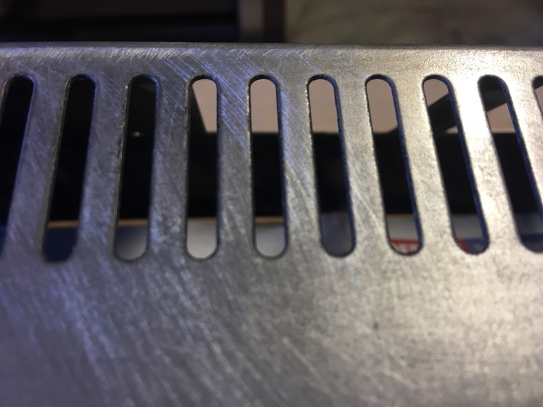
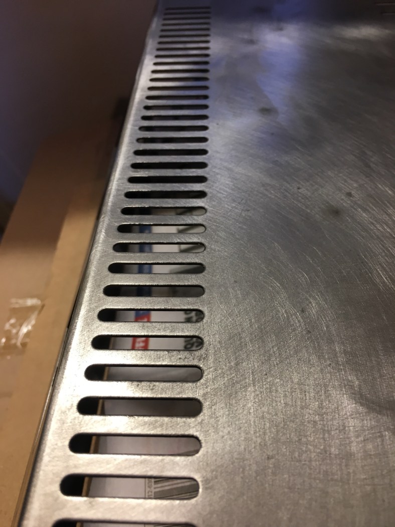
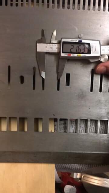
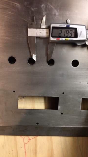
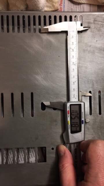
My trick was to throw an LED light source underneath the panel and simply get it to shine thru and look at where the holes were, and see where the decals lined up. It seemed to move more and more out of alignment as I moved across the panel once I lined it up on the left side. It was out by around 8-9mm by the right hand side. Lucky I had not gone straight to film! If I lined up from the centre of the panel, then the sides were only out by 3-4 mm in places. I started to suspect the printer had not printed 100% to scale, or that my photos that I took to use for lining up the decal were suffering from a small degree of “fisheye”, which causes this exact problem…things start to be more and more out on the sides when this problem is present and that was what seemed to be happening. But I made adjustments and movements anyway assuming the print was correct. But this time for the next print I would also add a tape measure ruler incorporated into the graphic all the way along the edge in mm to be able to confirm the print was accurate. (Something i should have done in the first place really if I was thinking ahead). I really thought the first print would be perfect and that would be all I needed! Wishful thinking indeed.

The way around any photo fisheye i discovered is to stand as faaarrr away from the subject as possible, and to use a lens that zooms in as much as you can. The further away you stand when taking a pic, the less fish-eye. So you need a good lens and high res camera to get the job done. An iphone camera won’t cut it.

Ok tweaks done …and off to the printers again for a second try, and now with the built in measuring ruler to see if it was indeed accurate.

Here is what it looks like in Coreldraw with the SLR photo of the tracing paper beneath:

This is how I can determine the position of decals… the SLR photo is lined up with the decal design exactly the same as it was printed. (The holes in the panel can be seen as white). Then the decal designs are moved around so that they are lined up with the corresponding white hole correctly. I’m sure there’s a more technically correct way to do it. But this is my way, it was more fun than just taking measurements and punching in numbers somewhere …and it worked. And then just before you go to print again, you remove the underlaid image of the transfer paper to just leave the decal vector image:

So second time I was much closer …95% there. And the printer was dead-on accurate with its scaling … the printed measuring tape was lining up perfectly with the real one which was good news and dispelled any concern there. So i was in the ballpark for sure.
I made the last few tweaks to the file but it would need to be printed a 3rd and final time to confirm dead-on accuracy for all of the graphics and to supply to the decal workshop. I wanted to be able to say “here is the file, and here is a print out of the file, as you can see it lines up perfect so don’t try and tell me the file is out if there’s alignment problems.”. From experience , Jeff told me, the workshops always blame the file when they screw up. You can see the ruler on this image below, that was printed out across the bottom in yellow this time to confirm printing size accuracy. And you can make out the panel shadows on this pic underneath the tracing paper…perfectly lined up with the decal. Yay!

Time to finally visit the decal screen printing workshop!
Meanwhile it gives me great pleasure to announce that Jeff has kindly agreed to allow the file that is the combination of both our hard work to be uploaded here for all Jupiter 8 owners who have rusty panels they want to fix. A BIG thanks to you from everyone in the Jupiter 8 community Jeff! You are a champion!
Some Notes: The art supplied is exactly how it appears originally on Coras panel before I stripped it, a Revision 1 Jupiter 8. The revision 2 has an extra label for the “DCB Port” on the rear that is not present on this art, and there may be other differences in spacing or positioning that Roland made so consider yourself on notice. You may also wish to make changes to the labeling. For instance I have made a change to Cora’s art because i know she will be receiving a Midi upgrade kit. So I have changed the clock sync switch to read “INT – EXT/MIDI”. All of the midi upgrade kits also require you to add a dodgy looking red momentary push button for control, which you will need to mount somewhere and drill a hole into your panel which I personally think looks like crap. So Cora has relinquished her front panel Tape “VERIFY” button for a label named “MIDI SETUP”. Finally on the rear underneath the jack outputs I have inconspicuously written Cora’s name on the decal art, because she asked me to do so 🙂 All of these changes were made post the files supplied here to avoid concern or confusion. If you want these changes I have described you will need to do them yourself to the file. However it is a unique opportunity for you to customize your Jupiter 8 panel if you are planning on following a similar path with your synth to Cora. Maybe you want to change the word “BENDER” to “EXPRESSION” for all I know. Well now is your chance. I don’t recommend going too crazy tho. You can start devaluing your synth if you stray too far away from the original look and vibe. But a few small personalizations can be fun !
Disclaimer: A lot of work has gone into establishing the accuracy of the content of these files. However the authors will not be held responsible for any inaccuracies that you believe to be present. In other words, it’s your responsibility to make sure they are aligned and accurate for your Jupiter 8 before screen printing. The alignment or accuracy has not been tested on every revision of the Jupiter 8 that was made.
Usage: These files are for your personal use only. Not for Commercial use or for sale. In other words, do not make money from them or from their use. They are free. Do not repost/upload these files onto other sites in this or a modified form thereof.
Okay Here we go:
This is what the final file looks like … each color layer separated out and marked:

High res PDF (for viewing) :
dwg file (AutoCad version – this is what the screen print workshop will often want to use) (zipped file):
EPS File [Some workshops will prefer to use this file]
AI Adobe Illustrator version [Saved in “Text as Curves” mode – With layers] :
Unlocked Coreldraw final file with layers (you can use to make changes if necessary) (zipped file)
If you find the file useful please thank Jeff personally. I am sure he will appreciate it. Here is his Facebook page:

 Cora The Corroder is now on Facebook! Now you can talk to her and ask her questions! Join her new Facebook group to be able to get updates on when new WordPress blog posts on her progress land (especially useful if you don’t have a WordPress account to subscribe through) as well as be able to ask questions and discuss her restoration with others ! Join now!


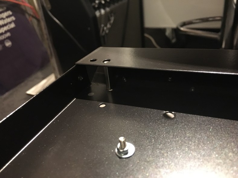


 After only a couple of hours we have a basic overview of the base panel rebuild up to now:


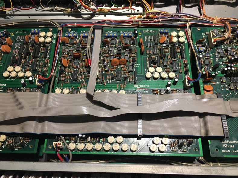


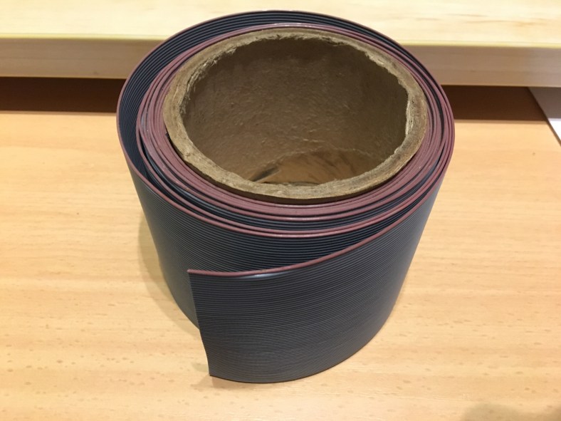


 This is why 50 (or more) core lead is the ideal choice as you can easily make up all of the lower generation sizes from it. You will need to buy lots of new black ribbon cable plugs of these sizes. They are not re-useable so all new ones are the order of the day, plus they are cheap and readily available everywhere and the old plugs are very likely oxidized inside and part of the problem. I highly recommend you treat your original cables very gently during this whole process, bend them as little as possible, there’s every chance the ones you are remaking could have some fault in your plug attachment process (which can be tricky affair), and you might need to revert to your original leads to track down a problem.
 If you are going to be making lots of ribbon cables up in the future then they are a worthy investment but for the few attachments we need to do for this job it’s just as effective to use a bench vice that had its claws covered in some gaffa tape to protect the plugs from damage in the attachment process. This is a completely legitimate method that many use for just a couple of plug attachments like we plan on doing:


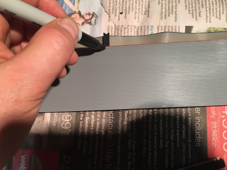


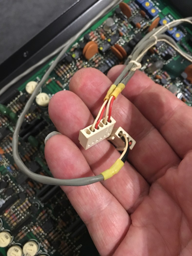
 you can see the plugs on the left are not aligned… and if the kink in the old original lead was completely removed it would look even more significant (I didn’t want to bend out the old lead completely in case it fell apart)


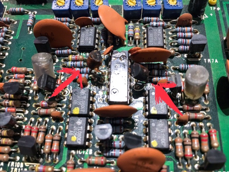


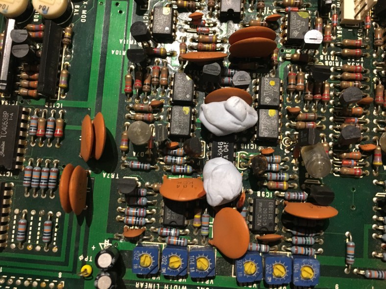
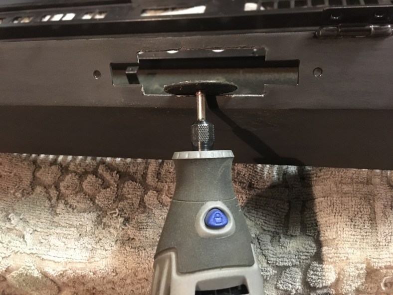
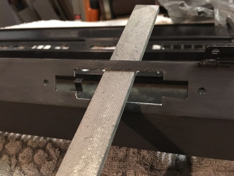
 Slicing carefully down the centre nice and slowly, bit by bit and being very CAREFUL not to wound any other adjacent components! It’s so easy to slip and slice a ceramic capacitor in half with one twist ! Also wearing a breathing mask as the old 80s dust could very well be carcinogenic. Taking no chances…
 A piece at the bottom having fallen off…then half the pins are out…one side to go…

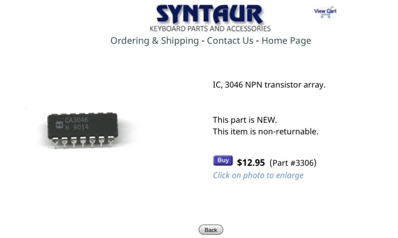
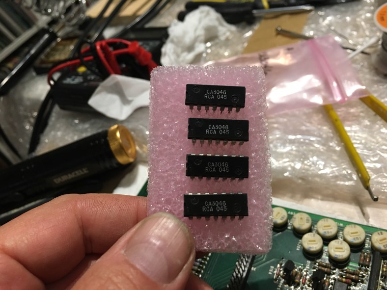
 Finally like an old rotten tooth from a 35 year old quarter horses’ mouth …3046 extracted !