
Building a battery pack from 18650 cells traditionally requires patience, a spot welder, and a supply of nickel strip. But what if there was another way? [Ben] is here with Cell-Lock, a modular battery assembly system.
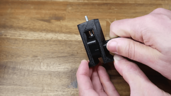
At the system’s heart are a set of interlocking end caps and connection pieces that function as locking cams as well as the electrical connections where needed. They were inspired by the cam systems used for furniture assembly, and are activated by rotation with a screwdriver. The result is a mechanically stable battery system in which different configurations can easily be assembled.
 We like that it doesn’t involve any heat near those cells; in part because we’ve seen our share of dodgy connections overheating. But we do have a few concerns. These include how reliable a connection those cams would make, as well as how much current they could safely take without overheating. If both of those could be addressed, we can see that this is an idea with a future.
You can see plenty of examples on the linked project, including an e-bike pack which seems to return no problems. Meanwhile this is by no means the first modular battery pack system we’ve seen.


 We find the nomenclature of these displays to be a bit confusing so let’s do a quick rundown. You may be most familiar with flip-dot displays, basically a dot-matrix grid of physical pixels that are black on one side and brightly colored (usually chartreuse) on the other. We saw


