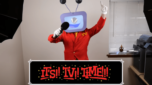
A Candle-Powered Light

For a little over two thousand years, the primary light sources after the sun had set were oil lamps and candles. This was well before the age of fossil fuels, so these oil lamps were often fueled with a labor-intensive agricultural product like olive oil. Candles were similarly difficult to make, made from tallow, beeswax, or even butter. Labor and materials costs aside, though, there’s a surprising amount of energy in these fuels and [Maciej Nowak Projects] has a generator that help these ancient light sources generate some electricity on the side.

The generator is based around a piece of technology called a thermoelectric generator (TEG), which produces a voltage potential when placed in a temperature gradient. These aren’t new technologies, but their typically low efficiencies limit where they can be effectively used. In this case, however, [Maciej Nowak] has gone to great effort to boost this efficiency as high as possible by using a huge radiator on the cool side of the TEG and another one on the hot side, which in this case is heated by a small tea candle. The electricity produced is sent to a tiny DC converter which regulates the voltage to 3.3V, which then powers two custom-built pedestal lamps on either side of the TEG, each with a high-efficiency LED mounted to a custom-made circuit board.

Although this is certainly not the first time a TEG has been set up to run a small lighting system, we do appreciate this one for its polish, design, and high efficiency. It would make a fitting addition to anyone’s emergency power outage kit as it really increases the amount of available light produced from any given candle. When taken to the extreme, though, thermoelectric generators can be made to produce a surprising amount of energy, provided they are placed in the right environment.

Continue reading “A Candle-Powered Light”

Meshtastic Does More Than Simple Communication

Meshtastic has been experiencing a bit of a renaissance lately, as the off-grid, long-range radio text messaging protocol gains a ton of new users. It’s been used to create mesh networks in cities, during disasters and protests, in small groups while hiking or camping, and for search and rescue operations. Although it’s connected plenty of people together in all of these ways, [GreatScott!] wanted to put it to work connecting some computing resources instead. He has a garden shed that’s too far for WiFi, so Meshtastic was used to connect it instead.

This isn’t a project to bring broadband Internet out to the shed, though; Meshtastic is much too slow for that. All he really wanted to do here was to implement a basic alarm system that would let him know if someone had broken in. The actual alarm triggering mechanism is an LED emitter-detector pair installed in two bars, one of which sends a 12V signal out if the infrared beam from the other is broken. They’re connected to a Heltec ESP32 LoRa module which is set up to publish messages out on the Meshtastic communications channel. A second module is connected to the WiFi at the house which is communicates with his Home Assistant server.

Integrating Meshtastic devices into Home Assistant can be pretty straightforward thanks to the various integrations already available, but there is some configuration to get these specific modules working as an alarm. One of the pins on the remote module had to be set up to watch the light bar, and although sending the alarm message out when this triggered worked well, the received signal never passed through to Home Assistant until [GreatScott!] switched to using the RadioLib library an an MQTT integration instead. But with perhaps more configuration than he planned for out of the way, [GreatScott!]’s alarm is up and running. Meshtastic projects often balloon into more than we had originally planned though, in more ways than one. You can follow along as our own [Tom Nardi] attempts to connect all of New Jersey with this new protocol.

Continue reading “Meshtastic Does More Than Simple Communication”

Electric Jeep With Modified Prius Hardware

On the list of cars widely regarded as the most reliable vehicles ever built, up there with the Toyota Land Cruiser, the Honda Civic, and the Mercedes W123 diesels, is the unassuming Toyota Prius. Although it adds a bit of complexity with its hybrid drivetrain, its design eliminates a number of common wear items and also tunes it for extreme efficiency, lengthening its life and causing minimal mechanical stress. The Prius has a number of other tricks up its sleeve as well, which is why parts of its hybrid systems are often used in EV conversions like [Jeremy]’s electric CJ-5 Jeep.

Inside the Prius inverter is a buck/boost converter used for stepping up the battery voltage to power the inverter and supply power to the electric motor. [Jeremy]’s battery is much higher voltage than the stock Prius battery pack, though, which means he can bypass the converter and supply energy from his battery directly to the inverter. Since the buck/boost converter isn’t being used, he can put it to work doing other things. In this case, he’s using it as a charger. Sending the AC from a standard EV charging cord through a rectifier and then to this converter allows the Prius hardware to charge the Jeep’s battery, without adding much in the way of extra expensive electronics.

There are some other modifications to the Prius equipment in this Jeep, though, namely that [Jeremy] is using an open-source controller as the brain of this conversion. Although this video only goes into detail on some of the quirks of the Prius hardware, he has a number of other videos documenting his journey to convert this antique Jeep over to a useful electric farm vehicle which are worth checking out as well. There are plenty of other useful things that equipment from hybrid and electric vehicles can do beyond EV conversions as well, like being used for DIY powerwalls.

Continue reading “Electric Jeep With Modified Prius Hardware”

Panoramic Film Camera Made From 3D Printed Parts

Even though digital cameras have lowered the barrier of entry to photography dramatically, as well as made it much easier for professionals and amateurs alike to capture stunning images without the burden of developing film, the technology behind them is considerably more complex than their analog counterparts. In fact, an analog film camera (not counting the lens) can be as simple as a lightproof box and a way to activate a shutter. Knowing that, any kind of film camera could be built for any number of applications, like this 3D-printed panoramic camera from [Denis Aminev].

The custom-built camera works by taking a standard roll of 35mm film, which is standardized to take 36 pictures, and exposing a wider section of the film to create a panorama. This reduces the number of pictures on the roll to 19. This is the fifth version of this camera, called the Infidex 176 V, and has everything a standard film camera would have, from an exposure counter, pressure plate for the film, a winder, interchangable lenses, a viewfinder, and a tripod mounting point. It does take a bit of work to assemble, as shown in the video linked below, but the final result is impressive and delivers a custom finished product not easily found or reproducible in off-the-shelf cameras.

The path to creating this camera was interesting as well, as [Denis]’s first custom film camera was a pinhole camera. From there he moved on to disassembling an SLR camera and attempting to reproduce all of its parts with 3D printed ones. With that in hand, he was able to modify this design into this panoramic camera which he likes because it reproduces the feel of widescreen movies. Although this camera reproduces all of the bells and whistles of a high quality analog camera, not all of these features are strictly necessary for taking pictures on film. Have a look at this minimum viable camera as well.

Continue reading “Panoramic Film Camera Made From 3D Printed Parts”

Custom VR Headset Uses Unconventional Displays

Cathode ray tubes (CRTs) are a fascinating display technology that has been largely abandoned outside of retro gaming and a few other niche uses. They use magnets to steer a beam of electrons rapidly across a screen, and while a marvel of engineering for their time, their expense, complexity, and weight all led to them being largely replaced by other displays like LCDs and LEDs. They were also difficult to miniaturize, but there were a few companies who tried. [dooglehead] located a few of the smallest CRT displays he could find and got to work putting them in the most unlikely of situations: a virtual reality headset.

The two displays for his headset come from Sony Watchmans, compact over-the-air black-and-white handheld televisions from the late 1900s. [dooglehead] had to create a method for sending video to these units which originally had no input connections, and then also used an FPGA to split a video signal into two parts, with one for each display. The two displays are placed side by side and attached to a Google Cardboard headset, with an off-the-shelf location tracker attached at the top. An IMU tracks head rotation while this location tracker tracks the motion of the unit through 3D space.

With everything assembled and ready to go, the CRT VR headset only weighs in a few grams heavier than [dooglehead]’s modern HTC headset, although it’s lacking a case (which is sorely needed to cover up the exposed high voltage of the CRTs). He reports surprisingly good performance, with notable interlacing and focus issues. He doesn’t plan to use it to replace any of his modern VR displays anytime soon, but it was an interesting project nonetheless. There are some rumors that CRTs are experiencing a bit of a revival, so we’d advise anyone looking to toss out an old CRT to at least put it on an online market place before sending it to a landfill.

Continue reading “Custom VR Headset Uses Unconventional Displays”

A Computer That Fits Inside A Camera Lens

For a long while, digital single-lens reflex (DSLR) cameras were the king of the castle for professional and amateur photography. They brought large sensors, interchangeable lenses, and professional-level viewfinders to the digital world at approachable prices, and then cemented their lead when they started being used to create video as well. They’re experiencing a bit of a decline now, though, as mirrorless cameras start to dominate, and with that comes some unique opportunities. To attach a lens meant for a DSLR to a mirrorless camera, an adapter housing must be used, and [Ancient] found a way to squeeze a computer and a programmable aperture into this tiny space.

The programmable aperture is based on an LCD screen from an old cell phone. LCD screens are generally transparent until their pixels are switched, and in most uses as displays a backer is put in place so someone can make out what is on the screen. [Ancient] is removing this backer, though, allowing the LCD to be completely transparent when switched off. The screen is placed inside this lens adapter housing in the middle of a PCB where a small computer is also placed. The computer controls the LCD via a set of buttons on the outside of the housing, allowing the photographer to use this screen as a programmable aperture.

The LCD-as-aperture has a number of interesting uses that would be impossible with a standard iris aperture. Not only can it function as a standard iris aperture, but it can do things like cycle through different areas of the image in sequence, open up arbitrary parts or close off others, and a number of other unique options. It’s worth checking out the video below, as [Ancient] demonstrates many of these effects towards the end. We’ve seen some of these effects before, although those were in lenses that were mechanically controlled instead.

Continue reading “A Computer That Fits Inside A Camera Lens”

Restoration Of Antique Clock With Unique Oscillator

The classic design of a mechanical clock generally consists of a display, a way to store energy, a way to release that energy at regular intervals, and a mechanism to transmit it where it needs to go. Most of us might be imagining a pendulum or a balance wheel, but there have been many other ways to maintain a reliable time standard with a physical object beyond these two common methods. This clock, for example, uses a rolling ball bearing as its time standard and [Tommy Jobson] discusses its operation in depth during a restoration.

The restoration of this clock, which [Tommy] theorizes was an amateur horological project even when it was new, starts by dismantling the clock nearly completely. The clock was quite dirty, so in addition to being thoroughly cleaned it also needed a bit of repair especially involving a few bent pins that stop the table’s rotation. These pins were replaced with stronger ones, and then everything in the clock’s movement was put back together. The tray carrying the ball bearing needed to be cleaned as well, and [Tommy] also added a lacquer to help preserve the original finish as long as possible. From there it was time to start calibrating the clock.

The ball bearing itself rolls back and forth along an inclined plane on a series of tracks. When it gets to the end it hits a lever which lets a bit of energy out of the movement, tilting the table back in the other direction to repeat the process. This is a much more involved process for getting an accurate time interval than a pendulum, so [Tommy] had a lot of work to do here. But in the end he was able to bring it back to life with an accuracy fairly close to a pendulum clock.

Ball bearings are a pretty popular medium for clock builds even in the modern era. This one uses them in a unique display, and a more recent version goes even further by using marbles to display digits directly.

Continue reading “Restoration Of Antique Clock With Unique Oscillator”