Tag Archives: WSPR

Updates to WSPR Lab

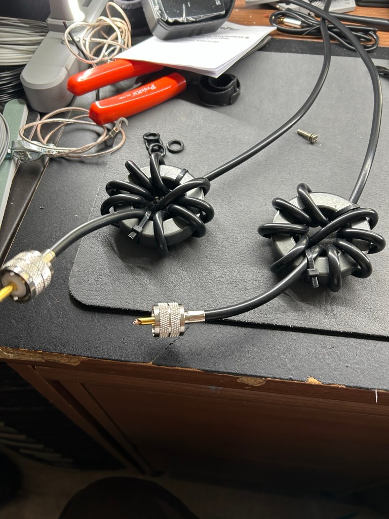
I added two Rf chokes consisting of 9 turns of rg-8x coax around an FT240-32 toroid to the inputs of the zbitx radios. I had to connect a keyboard and HDMI monitor to each radio to reconfigure the WiFi on each as I changed providers and routers since the last time I used it. Once configured I can access both via VNC.

I also fiddled a bit with the time setting issue I was having before and found a very simple fix. There is a configuration setting in Linux that has the machine wait until it connects to the network before proceeding with full startup. Enabling this allows the WiFi connection to be in place when the NTP service updates the time.

I have been running WSPR on the S9v31 vertical and collecting data on receive with no issues.

My remaining task is to build two identical feedlines and patch cables and I can setup my vertical antenna comparison.

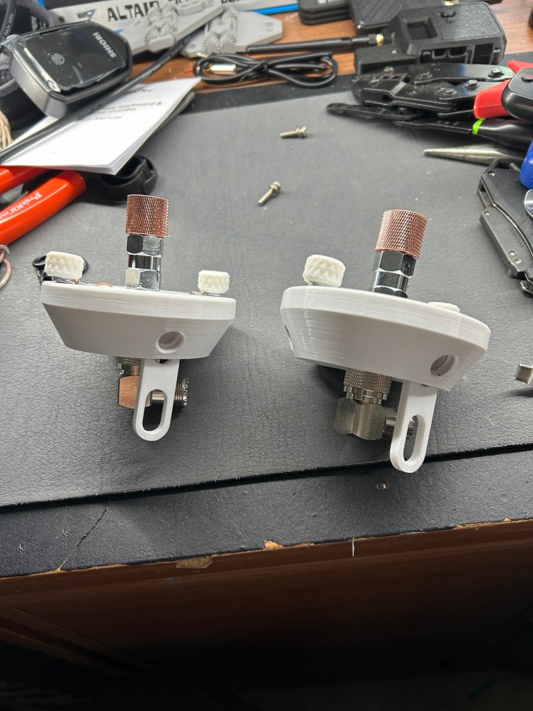
Two polypuck antena tripod hubs

I 3D printed two identical polypuck tripod hubs for use in WSPR experiments. I also made a total of four Rf chokes. Two will be used at the puck feed points and two were installed at the Rf inputs of the zbitx radios in the WSPR lab rack.

Each puck takes three 3/8” aluminum rods as legs. A telescopic whip will allow 20m and up resonant 1/4 wave antenna plus some planned variations. I’ll be using these to compare a 1/4 wave vertical with wire radials versus faraday cloth using these WSPR lab.

WSPR Lab Project

I am going to setup what may prove to be an interesting first project for the WSPR Lab. I plan to setup two JPC-12 vertical antennas one with ground mounted wire radials and the other with a piece of faraday cloth as the ground plane.

First Tests of WSPR Lab

I hooked up my end fed S9 vertical to one of the zbitx radios to make some initial tests of the WSPR Lab. I did run into a few snags:

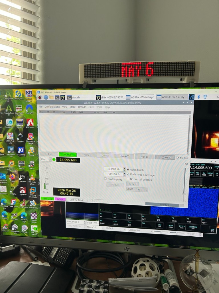
  1. The real time clock adjusted on each startup only impacts the zbitx system and not the operating system time. Since I am using WSJT-X for WSPR it needs to have the OS time synched. I solved this manually but have not been able to get NTP time synch working. If the time is not synched you will see signals on the waterfall but they will not be decoded.
  2. I tried transmitting on a 20% duty cycle at 2W. This would work…until it didn’t. I suspect a thermal dissipation issue. Over time the zbitx crashes and I cannot access it anymore over VNC resulting in needing to reboot it. I have a 12V fan installed on the top of the rack but the airflow is hitting the ATU’s and not the radios. I may need to rearrange the panels so the radios are on top. For now, limiting transmit to 1W seems to solve the issue.
  3. The number of received spots just feels low. I suspect I need to place some common mode chokes on the input to each radio. This is leading me down the rabbit hole of CM chokes in general and I’m looking at this in terms of the whole station. More on this to come.
  4. I am likely going to add a power switch to each radio so that they can be controlled independently. I’ll need to reprint the panels and do a bit of rewiring. I am also considering bringing the USB, HDMI, MIC, Key and Audio jacks for each radio to their own panel. This will allow more general purpose use but I’m not sure I need to go to the expense quite yet.

Nothing here is insurmountable but I will need to do a bit more work until this rais fully operational as a WSPR Lab.

WSPR Lab 3D Parts

The rack used for the WSPR Lab is by mklements on MakerWorld. The basic rack components are found in the bolted version. There are some additional components from Lab Rax Extension Side Panels & Post Joiner and from Lab Rax 1-5U Posts & Panels. The rack cages and panels were generated by an Openscad script provided by spuder also on MakerWorld. Many thanks to both mklements and spuder for their awesome models and scripts!

In order to customize the rack to meet the needs of the WSPR lab, several components had to be extensively modified. I had to combine two 3U vertical posts into a single 6U post. These were combined with a 2U post to make the entire rack 8U high. Side panels were modified to accept the DC buck converters and to meet the new height requirements. The rack cages and panels were generated using Spuder’s script and then modified in Fusion 360 to meet the requirements of the equipment. I have posted these modified parts on Thingiverse. Navigate to the projects tab on this blog site then select 3D parts by NO5V. Look for the entry labeled “WSPR Lab Custom Parts” for the STL and STEP files.

WSPR Lab Power Requirements

I did some tests on the WSPR Lab Power Draw requirements. The two radios in receive mode draw about 0.7A. This increases to about 1A when the ATUs are charging. I added a 12V 120mm fan to the top of the rack which adds about .45A. Adding the radio peltier coolers adds about 1.7A. Total current draw when receive only is 3.1A.

When transmitting at 5W the radios are drawing about 4A. When both are transmitting, they draw about 8A. Adding all the other bits drives all in, worst case current draw to just over 10.5A. My Power supply is rated to only 10A so I’ve order a 12V 15A to dedicate to the WSPR Lab.

If I am just doing WSPR receive experiments, I’ll be drawing about 1A without the fan running. This should be OK. Dual transmit operation will need cooling and as much as 10.5A. The WSPR Lab is portable but will not likely be very friendly for long periods of battery powered operations especially if trying to simultaneously transmit.

This all works well for me as I plan to run it indoors for long periods of time to collect WSPR data for comparison purposes.

WSPR Lab Complete

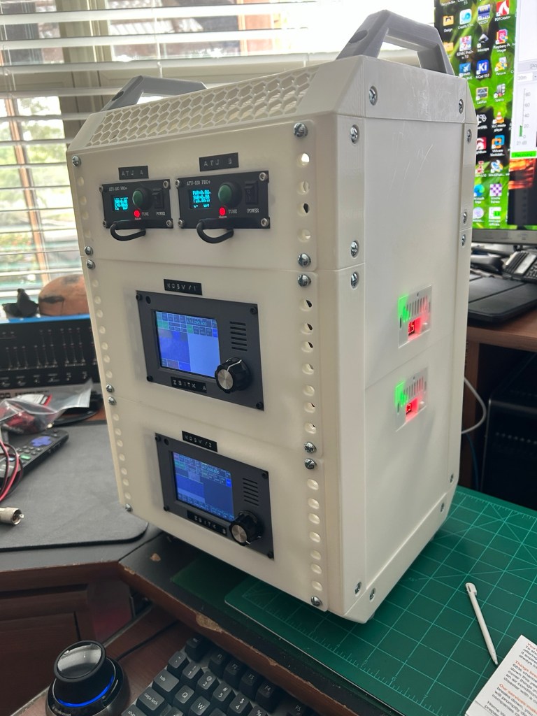
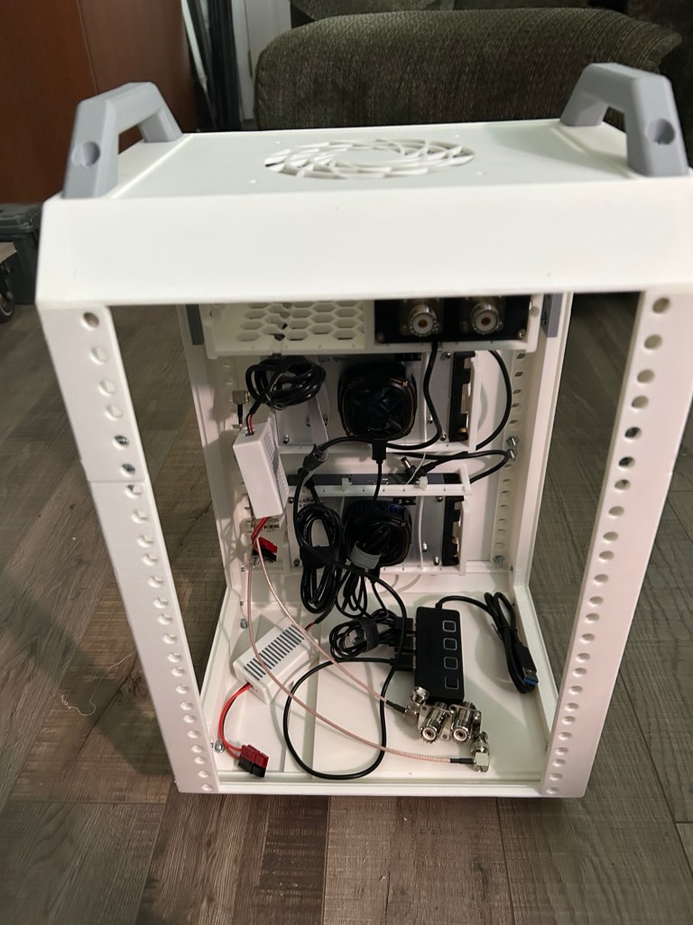
I finished assembling and wiring the WSPR Lab this morning. Here it is all powered up from a 12V, 5A power brick:

Once powered up, each radio can be accessed remotely using realVNC viewer. This allows running WSJT-X set in WSPR mode. I set the output power using a 50 ohm dummy load so that the radio reads 5W. Care should be taken not to transmit without a load attached! The antenna tuners are only needed if working with non-resonant antennas and are bypassed when switched off. Their internal batteries charge if needed.

Wiring is straight forward. Each radio is fed by a DC buck converter dropping the voltage to 8.5V. These can be seen mounted on the rack side. The two ATUs and radio cooling fans are connected to a four port, powered USB hub. A 12V to 5V converter is used to power the hub.

Now I need a couple of antennas to compare!

Progress on WSPR Lab

Here are a few images of the WSPR Lab as I print parts and assemble:

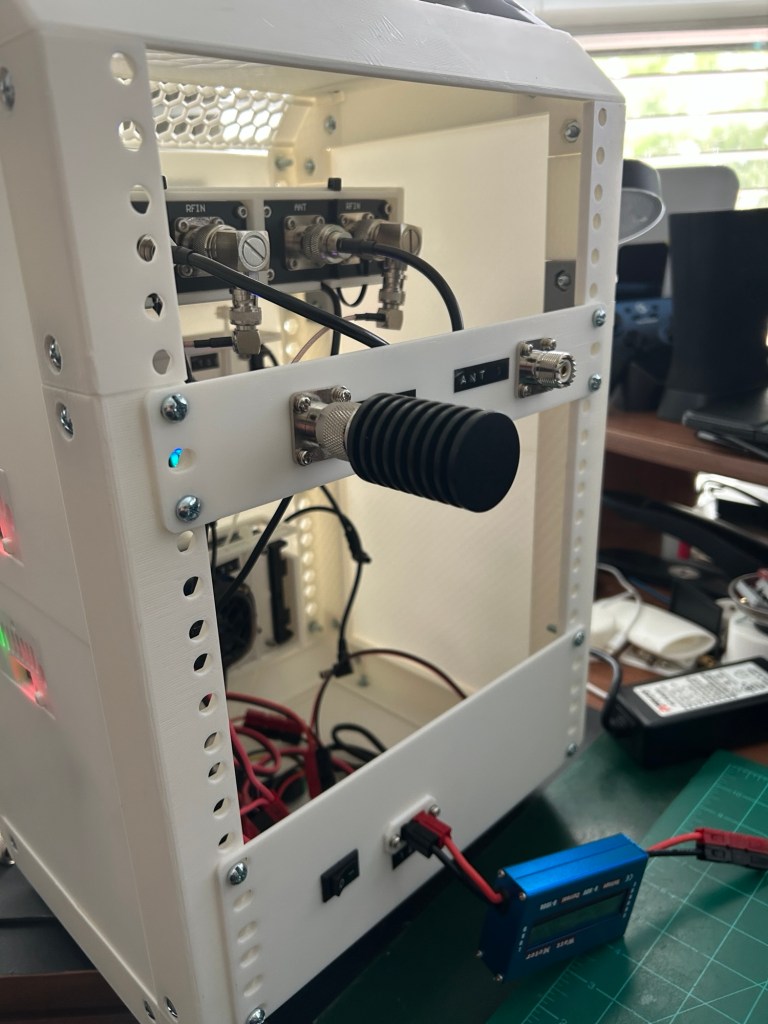
The rack is 8U tall and 10” wide. I have printed rack cages for the two zbitx radios and I’m showing the top 2U rack with one ATU-100 tuner installed for fit. Wiring is a bit messy right now. I’ll need to connect the two radios to the two tuners and then bring the UHF antenna outputs out the back. A four port powered USB hub provides power to the tuners and the peltier coolers on the radios. The hub is powered by a 5V supply. I’ll put a 12v to 5V buck converter to run that. The radios likewise have two 12v buck converters to provide the 8,5v the radios need. I’m going to integrate the cases into the side panels so I can view the supply voltage. The buck converters will be connected to Anderson power poles and a single switch to turn the whole thing on.

The rack is a design by mklements at MakerWorld. I’m using the bolted version with some mods to get it from 5U to an 8U rack. The rack cages are courtesy of spuder’s customizable rack case generator. Fusion 360 makes quick work of making mods to the standard parts to ensure a good fit.

Introducing the WSPR Lab

I have started working on a project I am calling the WSPR Lab. The idea is a self contained arrangement of equipment that I can use to transmit and receive WSPR on two different antennas simultaneously. The radios I am using are zbitx version 1 transceivers from HFSignals. These will be connected to separate antenna tuners so that non-resonant antennas can be compared. The whole system will be installed within a 10 inch, 3D printed rack. The rack will take two uhf connectors for antenna inputs and 12V Anderson’s power poles for power.

I’ll be able to deploy this system to gather comparative data on two separate antennas over time.

I have printed and assembled about 80% of the rack. I’m working on the rack faces and cages for the equipment. I’ll post some pictures soon as the project progresses.

Overnight WSPR performance of Shortened 40m Vertical

Here are some WSPR maps for the shortened 40m Vertical antenna:

The TX spots were at 2W. Overall pretty decent performance with SWR below 2:1 across the band. I’ve had to take the antenna down for now but will try again with the beam element added. I am waiting the arrival of some wire to cut the radials with.