This is a quick reference article where I test the Inno-maker IMX462 sensor on a Raspberry Pi 3. The scene is mostly dark, imagine a room with closed door and all windows covered up. The RPI3 is accompanied with 3 IR LEDs just to have at least some light once we start experimenting.
It’s important that we disable Automatic Exposure/Gain Control (AEC/AGC) and Auto White Balance (AWB) algorithms. We can do that with libcamera by using the exposure time (--shutter), the gain (--gain) and the white balance gains (--awbgains) settings. We need this for reproducability, but also for speed as some of these algorithm requires taking extra shots. Typically our command look as following:
With the shutter speed setting we control how long the image sensor gets to collect light. It’s often referenced as the exposure time. The longer the shutter speed, the more light is going to fall into the sensor, the more details we will get in our dark scene. Libcamera sets the shutter time in microseconds.
In dark conditions, a 1s shutter reveals some initial details. However, it is still too little to recognize anything. At 3s shutterspeed more details become visible and we can finally recognize objects. Bumping the shutter even higher means bringing even more details into the picture. Additionally we don’t notice a lot of noise in the picture. The only thing we do notice is that the picture becomes a bit white /pale.
Gain
The gain settings controls the combined analog and digital gain. But what is the difference the two? The analog gain comes into play inside the image sensor, where light is converted into an electrical signal (voltage), and then further on using an Analog-to-Digital Converter (ADC) into digital 1’s and 0’s. The analog gain amplifies the voltage signal before it goes into the ADC. In the resulting picture the amplification (referred to as ‘gain’) makes low light scenes appear brighter than without the extra gain.
There is however also a downside to this gain. The photo-detector is sensitive to dark noise, however from perspective of the amplifier this noise is indistinguishable from normal light that was collected in the photo-detector. Therefore the amplifier will also amplify the noise, and as such reduce the dynamic range. Normally the noise of the ADC will dominate over the noise introduced by the gain amplifier. However, as the gain is increased it will take the overhand at some point.
Digital gain is applied after the ADC stage, when the final image has been composed. The multiplication is performed on the digital values and as a result reduces the resolution. This process can be performed by some extra part in the image sensor, or an ISP, but it can also be achieved by post processing. Therefore it’s better not to apply any digital gain in your capturing pipeline as it actually discards some of the information that was captured in the analog stage. Without the digital gain you’re left with the option to apply the multiplication during your post processing stage.
The choice of analog vs digital gain is however not entirely ours to make. Using libcamera the --gain setting controls both. It’s up to the driver to actually decide what gain it will apply. But given the downside of using digital gain it will always prefer using analog gain over digital gain. Looking further in detail we actually see that image sensors have those analog and digital gain amplifiers embedded in hardware. They’re bound to a minimum and maximum value of amplification, which can than be controlled via the CCI (I2C) bus.
When we read the datasheet of the IMX462 we find that gain can be controlled within following rates:
0 dB to 29.4 dB: Analog Gain 29.4 dB (step pitch 0.3 dB)
29.7 dB to 71.4 dB: Analog Gain 29.4 dB + Digital Gain 0.3 to 42 dB (step pitch 0.3 dB)
In our tests we will avoid using digital gain. Lucky for use the linux driver for the IMX462 already ensures to have only control over the range of analog gain. Looking at the driver we notice that the range goes from 0 to 100, which maps to the ~30dB max and 0.3dB steps (30db/0.3dB = 100).
For our gain tests we fix the exposure time to 100ms.
It takes us up to a gain of 20 before we see any objects appearing in the background. And as we bump up the gain, more and more details will become visible. In some extend it’s similar to what we saw happening when we experimented with the exposure time. We could say that under the same conditions, using a 5s shutter with gain 1, roughly results in the same picture as when we use a 100ms shutter with gain 70.
The mayor difference though is that bumping up the gain also introduces a lot of noise in our pictures. At those higher gain values we can easily spot many horizontal bands and the picture quality is a lot worse than using the longer exposure shots. So if the shutter speed is allowed to go high than it will result in better picture quality in conditions where not a lot of light is available. In case you can’t allow the shutter to go high there is still the option to increase the gain but know that you will have to deliver in on image quality as noise gets amplified to. But in the end gain is also a way of bringing low light signals (like faint stars) into the picture. Keep in mind that from the results we’re mostly talking about the RAW data quality. No de-noising algorithms have been performed, though it could (and would) help to compensate some of the image quality loss of using the higher gain.
LCG vs HCG
The exposure and gain settings are 2 very common settings that you can find in most camera software, including libcamera, and as you can see it gives us quite accurate control over the camera sensor. There is however more to discover. The IMX462 has an extra trick up its sleeve: dual conversion gain. The IMX462 can choice between 2 conversion modes: Low Conversion Gain (LCG) and High Conversion Gain (HCG).
Do not confuse HCG/LCG with the normal gain setting that we saw previously. Those are 2 different things! The gain setting is about amplification, HCG/LCG is about photodiode to voltage conversion. So let’s say in LCG mode a bung of electrons convert to 0.01V, the same amount of electrons may convert in HCG mode to 0.05V. So with the same mount of light, a higher voltage is generated, hence why it’s called “high conversion gain”. In the end it will help in low light conditions.
Low conversion gain (LCG)
the normal mode
white is at 90% of pixel saturation
good for bright parts in the image
High conversion gain (HCG)
increases sensitivity and reduces readout noise level
has advantage in signal-to-noise (SNR) at low illuminance levels
good for dark parts in the image
So each gain mode has its own advantages, and they can even be combined by an ISP to achieve a higher dynamic range. There is very interesting topic at cloudynights about HCG. In the consumer market the IMX462 is used for example in the ZWO ASI462 camera. The reason I mention this is that they also advertise the HCG mode. In astro-photography this can play an important role. While HCG is implemented in the IMX462 in a different register than the normal gain setting, ZWO controls it automatically for you once the normal gain is increased to level 80. ZWO has their own gain levels compared to those of libcamera, so here 80 * 0.1dB = 8dB, where for libcamera 8dB gives a gain level of about 8dB * 0.3dB = 0.24dB. Always look at dB when comparing across vendors. Looking back at our previous gain experiments it would mean that if we also implemented auto LCG/HCG switching at the same levels, the switchover to HCG would already happen before noise is becoming dominant. It would also mean that on that moment we would see a big bump in brightness.
For the raspberry pi and libcamera things are currently a bit more complicated. As of November 2024 there is no out-of-the-box support for toggling HCG mode in video4linux, nor in libcamera. However, that doesn’t mean it’s impossible. HCG has already been discussed in a few topics on the raspberry pi forums and meanwhile a pull request (PR) has been opened for quite a bit of time that should allow control of HCG via a kernel module parameter. It means it doesn’t involve video4linux nor libcamera at all, but still if you’d ever need it you can enable it via the sysfs entries for the kernel module. A side effect of having the github PR is that the build server creates a build artifact that can directly be installed on your system. The PR is targetting linux 6.6 which is also the kernel that I’m currently on, so everything should go fairly straightforward. Note: you may not be able to install the build artifact by the time you read this article as the build server only retains the artifacts for few weeks/months.
Before you proceed in patching your kernel there is still one thing we need to take care off: patching libcamera itself. As you may have noticed from the kernel patches is that IMX462, due to small differences with IMX290, is from now on a individual camera device in the linux kernel. You can target the IMX462 specifically in your device tree while in the past you had to set it up as a IMX290/IMX327. So for the best user experience we should make sure to have the device tree overlay for IMX462 activated in the config.txt:
Now, about the licamera patches themselves I also need to shed some lights on what has been done. The patches are mandatory to make libcamera work with the “new” IMX462 camera driver. Libcamera wasn’t yet aware of this camera device since it never existed in earlier kernels. Libcamera would therefore exit with and error when you tried to take a snapshot. So I patched libcamera to support the new IMX462 cam and I created this PR on raspberry pi fork of libcamera so that the support will make it to the next Raspbian OS release. However it was concluded that the patches should better be upstreamed to the origin libcamera, and so that’s what I did. You can find them here:
The patches are merged upstream as we speak, so Raspbian will get the support for IMX462 out of the box anywhere soon, but due to merging strategies and the kernel dependency it’s rather hard to tell when exactly that will happen. Long story short, unless your OS already has the HCG kernel mode parameter in the sysfs (check if you have /sys/module/imx290/parameters/hcg_mode file) you’re on your own for patching your kernel and libcamera software.
If the rpi build artifacts are still available, at least you can already use the kernel as is. To install the patched kernel:
$ sudo rpi-update pulls/5859
This will take a few minutes to install. In my case the PR artifacts slightly upgrades to linux 6.6.57. If needed you can always switch back to a normal RPI kernel by updating to the latest version:
$ sudo rpi-update
Afterwards reboot the machine.
$ uname -a
Linux pycam3 6.6.57-v7+ #1 SMP Sat Oct 19 12:29:20 UTC 2024 armv7l GNU/Linux
The new kernel module entry can be found in the sysfs:
$ cat /sys/module/imx290/parameters/hcg_mode
N
By default it’s off, but you can enable/disable it by writing 0 or 1 to this file:
$ echo 1 | sudo tee /sys/module/imx290/parameters/hcg_mode
NOTE: the pics taken for the HCG experiments are performed with a slightly modified camera board. Do not directly compare them to those I took earlier. More details about the mods are upcoming, but essentially what I did is improving the quality of the power supply to the camera which on its turn reduces removes the horizontal banding that we can clearly see at high gain levels.
OK, now about the HCG mode, it’s pretty much clear that it makes the camera again more sensitive to light. At looks as if another level of analog gain is added, and actually it is said that HCG mode sort of brings an additional 5.8x gain. It also make noise stand out a bit more, so it’s not just something that magically fixes things for us. But if you look at it from another angle it just one more option in your toolbox as it allows us to see things in the dark as if we were using long exposure times, while actually the exposure time is set to only 100ms. Also compare the picture with HCG=on,gain=20 to the one with HCG=off,gain=50. Both pictures are pretty much the same in brightness, even though the gain levels are considerably different. Let’s zoom in a bit:
HCG off gain 50 vs HCG on gain 20, exposure 100ms
I’m not entirely convinced here but there seems to be a very small, subtle difference between both in that the one with HCG seems to be a tiny bit less noisy. Maybe it’s just the overall brightness that is a tiny bit off, or just some variation that we’re seeing. Anyway, I think it certainly deserves further exploring once I get back to trying astrophotography.
Conclusive thoughts
To conclude, we can state the IMX462 can be used in dark scenes. As a photographer, you have a few tools in your belt to get to the best possible result. There is a considerable range of exposure settings. Analog gain is available up to about 30dB. Finally, the High Conversion Gain can be enabled or disabled using the patches described in this article. I hope you found something interesting. At least for me, it was worth diving into this HCG thingy. It was also valuable to get some sort of reference picture quality on which I can compare my camera modifications. Regarding the latter, stay tuned for another article. It will go more into details on what you should do to get rid of the horizontal banding issues with the Inno-maker IMX462. See you soon.
Combining a Raspberry Pi and camera module is nothing new to most, but the linux internals are less well known. So let’s get uncomfortable and try to dive a bit deeper into the soft- and hardware stack that serves as a basis of many hacker projects worldwide.
When you get a camera board there is only one way to hook it up to your Raspberry Pi: through the MIPI-CSI 2 port. MIPI is an alliance that created the DSI (Display Serial Interface) and CSI (Camera Serial Interface) standards. CSI2 is an evolution of the CSI standard that brought RAW-16 and RAW-20 color depth and basically is one of the most important protocols to hook up your camera to your embedded computer board. RPIs and their camera boards come with a 15-pin or 22-pin connector. The 15-pin connector is mostly seen on standard Raspberry Pi models (A&B series) and Pi camera modules, while the 22-pin is on Raspberry Pi Zero-W and Compute Module IO Board. The connect in-between is called a Flat Flexible Cable (FFC).
So MIPI-CSI2 is a high speed data interface specially designed for cameras. It uses MIPI D-PHY, MIPI C-PHY, MIPI A-PHY on the physical layer. The basis is differential signaling on both the clock and data pairs, which are often referred to as ‘lanes’. Depending on the required bandwidth more data lanes can be added. The protocol is therefor serialized over one or multiple data pairs. The clock defines the speed at which the data is transferred and can be different depending on the camera attached. The CSI protocol is one-directional and therefor from a device topology stand of view we always speak of a CSI transmitter and CSI receiver. The transmitter is the camera transmitting pixel data, the receiver is the chip (SOC/FPGA/ASIC/…) taking the pixel data in for further processing. On top of the data lanes there is also a low speed I2C channel used for probing the camera and configuration. This channel is often referred to as the CCI (Camera Control Interface) channel. The picture below shows a CSI interface with 2 data lanes, one lane for the clock, and the I2C channel:
One thing you have to particularly understand here is that the data that goes through the CSI interface is pure sensor data. It doesn’t not like 24-bit or similar bitmap data that you’re familiar with. As said the receiver is most likely some SOC or FPGA that knows how to deal with the RAW data that it receives. It’s a feature of your SOC that you have to look for if it supports MIPI-CSI, which in case of a Raspberry Pi is fortunately the case. From there on the complexity only increases. Depending on your receiver the data may now travel directly into the video4 linux subsystem that is part of the linux kernel, or maybe makes a little detour through an ISP. The latter is a hardware accelerator for offloading the CPU in tasks that are focussed on improving image quality through all sorts for algorithms. The ISP (Image Signal Processor) can be internal on your SOC, but can also be an external chip that passes through data using MIPI-CSI while meanwhile performing a set of pre-defined image quality booster algorithms. That’s kind of the high level overview that you should keep in mind while we go through some of the detail.
Image courtesy of utmel.com
Sensor probing
MIPI-CSI is not a plug-and-play protocol in such way that you attach a sensor to your board and that you’re all settled. We can’t just go auto-detect the sensor without doing some driver specific magic and device tree configuration. As we already learned that’s where the I2C channels is used for. I2C off course is standardised, but the control registers of the sensors are not. Those is mostly hidden in a well protected datasheets or application notes that are not readily available. Sensor companies try to heavily guard their IP with NDA’s and so forth. So it’s not so straightforward to implement a new sensor into the kernel without the help of the manufacturer, unless you’re experienced in camera sensor drivers and are willing to spend some time hacking on its features.
Let’s start with defining the sensor. This typically happens in the device tree. Either directly as it is with most embedded systems (fixed purpose machines) or via device tree overlays as typically found in Raspberry Pi boards. With RPI is mostly a matter of adding the sensor device tree overlay into your boot config file. With other embedded systems is mostly adding the sensor specific config to your device tree that you compile together when you build the final image. Either way, the device tree description for both are the same, it’s just a matter of how the bootloader loads the data that is different. If you’re looking for documentation about the device tree configuration of the sensors that are supported by the linux kernel I can recommend open this link: https://www.kernel.org/doc/Documentation/devicetree/bindings/media/i2c/
So even though MIPI-CSI is the data interface, the sensors binding are found in the kernel under I2C as that is the protocol used for probing and controlling the sensors. Now let’s have a look at one of the popular sensors from nowadays, the imx290:
The Sony IMX290 is a 1/2.8-Inch CMOS Solid-state image sensor with
Square Pixel for Color Cameras. It is programmable through I2C and 4-wire
interfaces. The sensor output is available via CMOS logic parallel SDR output,
Low voltage LVDS DDR output and CSI-2 serial data output. The CSI-2 bus is the
default. No bindings have been defined for the other busses.
You have to define a bunch of required node properties, but there are also optional properties. Here is an example:
So what we can understand here is that you must add the sensor description to an existing I2C node which here is referred to as &i2c1.The sensor node itself will have a specif I2C address which in this case is 0x1a and is defined in thereg property. The compatible property is also important as this defines what driver will be loaded by the kernel once the sensor has been probed. Next make sure to set the correct value for the clock-frequency. Also set the correct supply voltages, and as seen in this examples there is also an optional reset pin that can be defined. Finally there is the port subnode with required endpoint subnode. This is the link to the MIPI-CSI! You can easily understand the amount of MIPI data-lanes in use here, and the remote-endpoint is the reference to the MIPI-CSI phy which is just another node in the device tree that describes the MIPI-CSI.
So by looking into this configuration we already learned a few important things. We know the I2C interface in use, we know which sensor will be loaded, at which I2C address it can be found and we know which MIPI phy it is connected too. We also know which drivers will be used. Now if we start looking into the linux kernel for which driver covers the sony,imx290 compatibility we end up here: imx290.c.
The driver for example mentions what device tree config it is compatible with:
As you can see the driver supports a few sensors all quite similar to each other, some have color pixels, other or just mono sensors.
The probing and removing functionality is often a means of allocating the according memory in the kernel. It also creates a new Video4Linux (V4L) subdevice, but more on that in a moment. It contains the I2C communication that goes over the Camera Control Interface (= the I2C control channel), look for function calls such as cci_write. Aside of that we also have power management functionality in the driver, the V4L streaming control, clocking/timing, passing through the V4L configuration commands (gain, format, etc.) to the sensor, and here and there some notes on how the sensor works.
/*
 * The IMX290 pixel array is organized as follows:
 *
 *     +------------------------------------+
 *     |           Optical Black            |     }  Vertical effective optical black (10)
 * +---+------------------------------------+---+
 * |   |                                    |   | }  Effective top margin (8)
 * |   |   +----------------------------+   |   | \
 * |   |   |                            |   |   |  |
 * |   |   |                            |   |   |  |
 * |   |   |                            |   |   |  |
 * |   |   |    Recording Pixel Area    |   |   |  | Recommended height (1080)
 * |   |   |                            |   |   |  |
 * |   |   |                            |   |   |  |
 * |   |   |                            |   |   |  |
 * |   |   +----------------------------+   |   | /
 * |   |                                    |   | }  Effective bottom margin (9)
 * +---+------------------------------------+---+
 *  <-> <-> <--------------------------> <-> <->
 *                                            \----  Ignored right margin (4)
 *                                        \--------  Effective right margin (9)
 *                       \-------------------------  Recommended width (1920)
 *       \-----------------------------------------  Effective left margin (8)
 *   \---------------------------------------------  Ignored left margin (4)
 *
 * The optical black lines are output over CSI-2 with a separate data type.
 *
 * The pixel array is meant to have 1920x1080 usable pixels after image
 * processing in an ISP. It has 8 (9) extra active pixels usable for color
 * processing in the ISP on the top and left (bottom and right) sides of the
 * image. In addition, 4 additional pixels are present on the left and right
 * sides of the image, documented as "ignored area".
 *
 * As far as is understood, all pixels of the pixel array (ignored area, color
 * processing margins and recording area) can be output by the sensor.
 */
Video4Linux
During the previous probing stage we already talked about the Video4Linux things that a camera driver needs to implement. You mat wonder what Video4Linux actually is. V4L is a kernel framework used to interface with video capture devices in Linux environments. It provides an API for handling various multimedia devices such as webcams, TV tuners, and digital cameras. Camera modules that are compatible with V4L can be easily integrated into Linux-based systems, allowing applications to capture and manipulate video streams from these devices. To make new kernel drivers for devices that need to be controlled through the Video4Linux framework there are a couple of APIs that you need to implement:
Device Discovery and Enumeration:
VIDIOC_QUERYCAP: This ioctl is used to query the capabilities of the device and determine if it supports V4L2.
VIDIOC_ENUM_FMT: Enumerates the supported video formats and frame sizes for the device.
Device Control:
VIDIOC_S_FMT and VIDIOC_G_FMT: Set and get the format of the video stream (resolution, pixel format, etc.).
VIDIOC_S_PARM and VIDIOC_G_PARM: Set and get parameters like frame rate, exposure, and other camera-specific settings.
Buffer Management:
VIDIOC_REQBUFS: Requests buffers to be allocated for video capture.
VIDIOC_QUERYBUF: Queries information about the allocated buffers.
VIDIOC_QBUF: Enqueues an empty buffer for capturing video data.
VIDIOC_DQBUF: Dequeues a filled buffer containing captured video data.
Streaming Control:
VIDIOC_STREAMON and VIDIOC_STREAMOFF: Start and stop video streaming.
Control Operations:
VIDIOC_QUERYCTRL: Query the supported controls (e.g., brightness, contrast, zoom).
VIDIOC_G_CTRL and VIDIOC_S_CTRL: Get and set control values.
Event Handling:
VIDIOC_DQEVENT: Dequeues events from the event queue.
VIDIOC_SUBSCRIBE_EVENT: Subscribes to specific V4L2 events.
But if you carefully examined the imx290.c driver you won’t find any of these API. That’s because most of the V4L APIs have been abstracted away. Camera sensor developers don’t need to implement the video4linux APIs (like VIDIOC_QUERYCAP, VIDIOC_S_FMT, VIDIOC_G_FMT, etc.) and ioctl’s directly, things are abstracted away through functions pointers and structs that define what the sensor is capable of and how to handle specific operations. Important here is that the sensor is a Video4Linux Subdevice! There reason it’s called subdev is because the sensor is mostly part of a bigger camera system by means of some other media controller. Subdevices have specific subdevice operations related to sensor configuration, stream management, and control. Camera control (like exposure, gain, etc.) is often managed through the V4L2 control framework, and V4L provides a mechanism to register, find, and get/set control values without direct ioctl handling in the driver file itself. The core of the driver usually consists of function pointer structures like v4l2_subdev_ops, which include pointers to functions that handle specific tasks:
core: Basic operations like initialization and shutdown.
pad: Operations related to media pads (connections between components in the media controller framework).
video: Includes functions for setting/getting video stream parameters.
sensor: Might include functions specific to sensor configuration and control.
Also understand that the driver initializes these structures and registers itself with the V4L2 framework, which in turn handles the ioctl calls from user space. This registration process binds the driver’s operations with the V4L2 infrastructure, making direct ioctl implementation unnecessary in the driver file itself. The imx290 is a good example in that regard. For example notice this part of driver where the video operations are described:
Now let’s look at the specific function the driver hooks into the V4L video ops for the s_stream function:
static int imx290_set_stream(struct v4l2_subdev *sd, int enable)
{
	struct imx290 *imx290 = to_imx290(sd);
	struct v4l2_subdev_state *state;
	int ret = 0;

	state = v4l2_subdev_lock_and_get_active_state(sd);

	if (enable) {
		ret = pm_runtime_resume_and_get(imx290->dev);
		if (ret < 0)
			goto unlock;

		ret = imx290_start_streaming(imx290, state);
		if (ret) {
			dev_err(imx290->dev, "Start stream failed\n");
			pm_runtime_put_sync(imx290->dev);
			goto unlock;
		}
	} else {
		imx290_stop_streaming(imx290);
		pm_runtime_mark_last_busy(imx290->dev);
		pm_runtime_put_autosuspend(imx290->dev);
	}

	/*
	 * vflip and hflip should not be changed during streaming as the sensor
	 * will produce an invalid frame.
	 */
	__v4l2_ctrl_grab(imx290->vflip, enable);
	__v4l2_ctrl_grab(imx290->hflip, enable);

unlock:
	v4l2_subdev_unlock_state(state);
	return ret;
}
Specifically spot the imx290_start_streaming() and imx290_start_streaming() function calls. It probable needs little explanation that this is how the V4L is hooked into the driver to start and stop the streaming of data. Diving even deeper we see that the imx290_start_streaming function for instance sets up a registor map, next it sets up the MIPI-CSI data lanes (see imx290_set_data_lanes) and clock (see imx290_set_clock), it sets the format (see imx290_setup_format), and finally writes over the CCI (=I2C) bus the very specific imx290 register values that command the sensor to start streaming:
The nice thing about V4L is that the entire knowledge of how this specific sensor needs to be handled (registers, formats, csi setup, …) is within the driver, and not scattered throughout the kernel as #ifdef’s or whatever.
Data streaming
After the camera has been probed and configured through its registers (see step 1 in the below) we’re ready to pick up the visual data using the V4L calls we just described. As already explained this data doesn’t go through the CCI, but instead through the CSI lanes into a CSI receiver. This receiver can be an ISP (Image Signal Processor), or some embedded CSI receiver that’s part of the SOC of your choice. One example of such receiver is the one build into the Raspberry-Pi, here the block is called “unicam”. See step 2 in the below.
CSI drivers are similarly to camera drivers not always open source or openly documented, and sometimes downstream maintained. But let’s try to focus a bit on Raspberry Pi here. Each of the different RPI versions come with a different Broadcom SOC (but it all started with the Broadcom BCM2835). From a camera perspective nothing too fancy has changed since the first version, apart from the Raspberry Pi 5 which added some extra dedicated camera pre-processor. The CSI receiver has throughout the years always been referred to as the “unicam” CSI receiver, and is actually part of the VideoCore 4 GPU. The drivers are found in the downstream Raspberry Pi fork of the linux kernel, but no open documentation is available outside of that driver. Very recently there has been put some effort into upstreaming the driver to make it more video 4 linux compliant. For the current driver that’s still shipped with the RPI images look at the RPI linux kernel sources. Reading those driver sources learns you a thing or two about how everything has been put together. Actually the CSI block can either be accessed via 2 ways. One way is via the bcm2835-camera driver (that resides in linux staging). Here the VideoCore 4 GPU firmware handles roughly the entire camera pipeline: camera sensor, unicam, ISP, and delivers fully processed frames. Aside of being entirely closed source, there is another important downside to the solution: it only supports 2 or 3 image sensors that Broadcam was asked to support. The second option is via the unicam linux driver, see:
This driver is able to connect to any sensor with a suitable output interface and V4L2 subdevice driver. This driver handles the data it receives over CSI and copies it into SDRAM. The data is typically in raw Bayer format and the driver doesn’t perform nearly any processing on the data stream aside of repacking. One other aspect of the driver is image format selection. Aside of Bayer other formats are also supported by the unicam driver, e.g. several RGB, YUV and greyscale formats are also mentioned. And of course probing the unicam device is also part of the driver/device bring-up. The main goal of this new driver is leveraging more on the V4L framework, and through that become a lot more flexibility compared to the Broadcom proprietary solution. This option is the off course the most preferred. Understand that both driver solutions are mutual exclusive, thus only one of the two is active at the same time. To select the RPI Foundation kernel driver solution just make sure to make the correct device tree configuration. The RPI driver will be picked up as long as the correct device tree bindings have been defined.
If you want to dive into the new bcm2835-unicam driver you’ll off course recognize many of the same concepts as for the camera drivers, but also some new stuff:
device tree mapping
probing
video4linux device creation
connecting to v4l subdevices
start/stop streaming
part of those functions actually ask the sensor subdevice to start streaming: ret = v4l2_subdev_call(dev->sensor, video, s_stream, 1);
create storage buffers in RAM for the incoming sensor data
ex: spot the usage of VIDIOC_CREATE_BUFS ioctl (vidioc_create_bufs)
arrays of supported video formats
Bayer data
Before we go further on the image pipeline let’s first get a quick understanding on what Bayer data is. When reading some of my previous articles about astro-photography we kind of explained how image sensors are build up. They’re like little buckets in which light is collected into tiny photo diodes, and than there is some extra circuitry that converts this electricity into digital values that are transmitted over CSI. The ‘pixels’ can either by mono colored, or RGB through small light filters applied to each pixel individually. It’s not the RGB data that we know in userspace, since each pixel senses only one aspect of the incoming light.
The Bayer filter isn’t always layed out int the same way, it changes over brands and models of sensors, but nearly always packs 2 our of 4 pixels in green as that is what humans are most sensible to.
Per pixel there is an analog-digital conversion that tell us how much light entered the pixel. It’s not a simple per pixel on-off but instead gives us a value in the range of 8 to 16 bits per pixel. The range differs per each sensor. So if we would take a picture and represent the raw Bayer data, and then zoom in so that we can see the individual pixels, than it would look roughly like something in the below.
For us the Bayer data by itself is clearly far from what we see in the real world. The image contains noise and the brightness is linear, and it appears for more greener that what you would see in the real world. Further processing needs to be performed. Astro and professional photography fanatics may want to grab the pure raw data directly and perform the image processing themselves in professional software like Photoshop, Siril, etc… Others want to get the picture perfect immediately without post-processing, for example for CCTV purposes, or perhaps in a digital camera such as your smart phone.
ISP: Image Signal Processor
So when the final image result needs to be anything close to how we preserve reality we still have a long way ahead of us. The ISP, short for Image Signal Processor, is a dedicated block of hardware that’s able to perform complex image correction algorithms on the raw image data. The ISP can be an external chip or an internal block as with the Broadcom GPU that’s used on the Raspberry Pi. The ISP can be simple and cheap, but they can also cost several tens of euros per chip and perform intens algorithms like dewarping. Sometimes the signal processing can even be performed in an FPGA or even on the main CPU though means of a SoftISP. According to Bootlin the most important aspects of the ISP are:
De-mosaicing: interpreting the RAW Bayer data
Dead pixel correction: discard invalid values
Black level correction: remove dark level current
White balance: adjust R-G-B balance with coefficients/offsets
Noise filtering: remove electronic noise
Color matrix: adjust colors for fidelity
Gamma: adjust brightness curve for non-linearity
Saturation: adjust colorfulness
Brightness: adjust global luminosity
Contrast: adjust bright/dark difference
A common task for ISP is running the so called triple-A algorithms:
Automatic exposition: manage exposure time and gain (optionally diaphragm)
Auto-focus: detect blurry and sharp areas, adjust with focus coil
Auto white balance: detect dominant lighting and adjust
A picture will perhaps explain it a lot better here:
To be clear, not all stages have to be performed, it really depends on the application that you’re targeting. But the less processing you perform, the more closer you get to the RAW sensor data which in most cases will be pretty disappointing. An important part of the end result is proper calibration and pipeline tuning. Mostly the hardware ISPs are closed sourced: a black box that takes some tuning params. There is however also the software ISP (ex: libcamera-softisp) that allows you to run these algorithms on a broader range of platforms. Here the RAW Bayer data is collected directly from the V4L framework into userspace where it can be further processed. The soft ISP is very flexible in design, but know that for low latency or high speed processing the hardware ISP is mostly the preferred choice. There are even attempts to run these algorithms on the GPU instead of VPU or CPU as GPUs come with general purpose computing stacks nowadays for fast parallel (per pixel) processing, allowing the flexibility of a software ISP at nearly the speed of a hardware ISP. But nothing comes for free though, understand that GPUs in general consume more power than dedicated hardware ISPs do.
Entire books can be written about all the algorithms that are out there, and the many different implementations that they have. If you want to start diving into this matter and learn something about camera tuning I can encourage you going through the awsome Raspberry Pi Camera Guide.
Oh, and did you know, for a Raspberry Pi:
In fact, none of the camera processing occurs on the CPU (running Linux) at all. Instead, it is done on the Pi’s GPU (VideoCore IV) which is running its own real-time OS (VCOS). VCOS is actually an abstraction layer on top of an RTOS running on the GPU (ThreadX at the time of writing). However, given that RTOS has changed in the past (hence the abstraction layer), and that the user doesn’t directly interact with it anyway, it is perhaps simpler to think of the GPU as running something called VCOS (without thinking too much about what that actually is).
So technically there is a lot that comes into play. Please read the Picamera docs to learn something more about how it grabs image data through the legacy stack.
From kernel to Userspace
User space applications interact with the /dev/videoX device files using standard file operations (open, read, write, ioctl, etc.). These are interfaces created by Video4Linux. When an application performs operations on the /dev/videoX device file, these operations are handled by the V4L2 framework in the kernel. An import thing about the kernel driver is the V4L Device Node Creation: after a driver has successfully registered, the V4L2 framework handles the creation of the device node (/dev/videoX) in the filesystem. The registration typically looks like this:
    ret = video_register_device(&vdev, VFL_TYPE_GRABBER, -1);
    if (ret < 0) {
        v4l2_device_unregister(&v4l2_dev);
        return ret;
    }
The video_register_device() function is key for creating the device node. The V4L2 framework automatically handles the creation and linking of the device file under /dev based on this registration. The device file naming (/dev/video0, /dev/video1, etc.) is managed by V4L2 and the order depends on the sequence and number of video devices registered. Typically /dev/video0 is the one closest to the camera sensor and is also the one that would give you most likely RAW sensor data.
User space applications interact with this device file using system calls (open, ioctl, mmap, etc.). The driver will contain handles for each of these calls. If we again look at the bcm2835-unicam driver we recognize exactly the structure of doing such things:
Looking at the open functionality, we see that there is code in place to power-on the sensor:
        ret = v4l2_fh_open(file);
	if (ret) {
		unicam_err(dev, "v4l2_fh_open failed\n");
		goto unlock;
	}

	node->open++;

	if (!v4l2_fh_is_singular_file(file))
		goto unlock;

	ret = v4l2_subdev_call(dev->sensor, core, s_power, 1);
	if (ret < 0 && ret != -ENOIOCTLCMD) {
		v4l2_fh_release(file);
		node->open--;
		goto unlock;
	}
The read functions however is not part of the unicam driver but instead standardised in V4L. In the framework data is made available by memory mapping which avoids copying the data various times throughout the pipeline. Especially also look at mmap = vb2_fop_mmap. The vb2_fop_mmap function is specifically designed to handle the mmap file operation for video devices using the vb2 library. It maps the video buffers, which have been allocated in the kernel space, into the user space so that applications can directly access them. This is crucial for performance in video capture and output applications because it allows user space processes to access hardware-acquired video frames without copying data between kernel and user space, thus minimizing latency and CPU load.
USB Video
Small intermezzo: if you’re using a USB camera instead of the CSI Camera Module, the device is likely handled by a generic UVC (USB Video Class) driver called uvcvideo. This is the standard Linux V4L2 driver for USB video class devices. It automatically creates a /dev/videoN device when a UVC-compatible USB camera is plugged in. The interesting thing here is that you avoid any needs of writing special drivers. However, mostly you’ll be running some USB capable FPGA on the other side of the USB cable that is either pre-tuned well but often also comes with some userspace tools to adjust the calibration. And you have to implement the UVC protocol and so forth, so it’s not entirely without trade-offs. For embedded devices the the preferred choice is mostly MIPI-CSI, if you want to have a plug-and-play solution than USB could be a solution.
Userspace
The final step is to look at how user space applications exactly need to handle the V4L subsystem. The best thing we can do here is write our own application and see if it works.
/**
 * @file capture.c
 * @author Geoffrey Van Landeghem
 * @brief
 * @version 0.1
 * @date 2024-05-09
 *
 * @copyright Copyright (c) 2024
 *
 * Simple application that captures a bunch of camera frames
 * using memory mapping, and saves the 5th frame to disc.
 * The output file is called frame.jpg.
 * The camera input device is /dev/video0.
 *
 * Compile:
 * $ gcc -o capture capture.c
 *
 * Run:
 * ./capture
 *
 * Based upon https://www.kernel.org/doc/html/v4.14/media/uapi/v4l/capture.c.html
 */


#include <stdio.h>
#include <stdlib.h>
#include <string.h>
#include <fcntl.h>
#include <errno.h>
#include <sys/ioctl.h>
#include <linux/videodev2.h>
#include <unistd.h>
#include <sys/mman.h>

#define VIDEO_DEV "/dev/video0"
#define OUTPUT_IMG "frame.jpg"
#define STORE_AFTER_X_FRAMES 5

static int _fd = 0;
static void* _buffer = NULL;
static unsigned int _len_buff = 0;
static int frames_received = 0;

static int open_device(void)
{
    fprintf(stdout, "Opening video device '" VIDEO_DEV "'\n");
    _fd = open(VIDEO_DEV, O_RDWR | O_NONBLOCK, 0);
    if (_fd < 0) {
        perror("Failed to open device");
        return errno;
    }
    return 0;
}

static int init_device(void)
{
    fprintf(stdout, "Querying capabilities device\n");
    struct v4l2_capability cap;
    if (ioctl(_fd, VIDIOC_QUERYCAP, &cap) < 0) {
        perror("Failed to get device capabilities");
        return errno;
    }
    fprintf(stderr, "- DRIVER: %s\n", cap.driver);
    fprintf(stderr, "- BUS INFO: %s\n", cap.bus_info);
    fprintf(stderr, "- CARD: %s\n", cap.card);
    fprintf(stderr, "- VERSION: %d\n", cap.version);
    if (!(cap.capabilities & V4L2_CAP_VIDEO_CAPTURE)) {
        fprintf(stderr, "The device does not support video capture.\n");
        return -1;
    }
    if (!(cap.capabilities & V4L2_CAP_STREAMING)) {
        fprintf(stderr, "The device does not support video streaming.\n");
        return -1;
    }

    fprintf(stdout, "Setting image format\n");
    struct v4l2_format format;
    format.type = V4L2_BUF_TYPE_VIDEO_CAPTURE;
    format.fmt.pix.width = 640;
    format.fmt.pix.height = 480;
    format.fmt.pix.pixelformat = V4L2_PIX_FMT_MJPEG;
    format.fmt.pix.field = V4L2_FIELD_INTERLACED;
    if (ioctl(_fd, VIDIOC_S_FMT, &format) < 0) {
        perror("Failed to set format");
        return errno;
    }
    return 0;
}

static int init_mmap(void)
{
    fprintf(stdout, "Requesting buffers\n");
    struct v4l2_requestbuffers req = {0};
    req.count = 1;
    req.type = V4L2_BUF_TYPE_VIDEO_CAPTURE;
    req.memory = V4L2_MEMORY_MMAP;
    if (ioctl(_fd, VIDIOC_REQBUFS, &req) < 0) {
        perror("Failed to request buffers");
        return errno;
    }

    fprintf(stdout, "Memory mapping\n");
    struct v4l2_buffer buf = {0};
    buf.type = V4L2_BUF_TYPE_VIDEO_CAPTURE;
    buf.memory = V4L2_MEMORY_MMAP;
    buf.index = 0;
    if (ioctl(_fd, VIDIOC_QUERYBUF, &buf) < 0) {
        perror("Failed to query buffer");
        return errno;
    }
    fprintf(stdout, "Buffer length: %u\n", buf.length);
    _len_buff = buf.length;
    _buffer = mmap(NULL, buf.length, PROT_READ | PROT_WRITE, MAP_SHARED, _fd, buf.m.offset);
    if (_buffer == MAP_FAILED) {
        perror("Failed to mmap");
        return errno;
    }
    return 0;
}

static int start_capturing(void)
{
    fprintf(stdout, "Capturing frame (queue buffer)\n");
    struct v4l2_buffer buf;
    buf.type = V4L2_BUF_TYPE_VIDEO_CAPTURE;
    buf.memory = V4L2_MEMORY_MMAP;
    buf.index = 0;
    if (ioctl(_fd, VIDIOC_QBUF, &buf) < 0) {
        perror("Failed to queue buffer");
        return errno;
    }
    fprintf(stdout, "Capturing frame (start stream)\n");
    enum v4l2_buf_type type = V4L2_BUF_TYPE_VIDEO_CAPTURE;
    if (ioctl(_fd, VIDIOC_STREAMON, &type) < 0) {
        perror("Failed to start capture");
        return errno;
    }
    return 0;
}

static int process_image(const void *data, int size)
{
    fprintf(stdout, "Saving frame to " OUTPUT_IMG "\n");
    FILE* file = fopen("frame.jpg", "wb");
    if (file == NULL) {
        perror("Failed to save frame");
        return -1;
    }
    size_t objects_written = fwrite(data, size, 1, file);
    fclose(file);
    fprintf(stdout, "Stored %lu object(s)\n", objects_written);
    return 0;
}

static int read_frame(void)
{
    struct v4l2_buffer buf;
    unsigned int i;
    buf.type = V4L2_BUF_TYPE_VIDEO_CAPTURE;
    buf.memory = V4L2_MEMORY_MMAP;
    fprintf(stdout, "Capturing frame (dequeue buffer)\n");
    if (ioctl(_fd, VIDIOC_DQBUF, &buf) < 0) {
        if (errno == EAGAIN) return 0;
        perror("Failed to dequeue buffer");
        return errno;
    }

    frames_received++;
    fprintf(stdout, "Frame[%d] Buffer index: %d, bytes used: %d\n", frames_received, buf.index, buf.bytesused);

    if (frames_received == STORE_AFTER_X_FRAMES) {
        process_image(_buffer, buf.bytesused);
        return 1;
    }

    if (ioctl(_fd, VIDIOC_QBUF, &buf) < 0) {
        perror("Failed to queue buffer");
        return errno;
    }
    return 0;
}

static int main_loop(void)
{
    unsigned int count = 70;
    while (count-- > 0) {
        for (;;) {
            fd_set fds;
            struct timeval tv;
            int r;

            FD_ZERO(&fds);
            FD_SET(_fd, &fds);

            /* Timeout. */
            tv.tv_sec = 2;
            tv.tv_usec = 0;

            r = select(_fd + 1, &fds, NULL, NULL, &tv);

            if (-1 == r) {
                if (EINTR == errno)
                    continue;
                perror("Failed to select");
                return errno;
            }

            if (0 == r) {
                perror("Select timed out");
                return errno;
            }

            if (read_frame())
                break;
            /* EAGAIN - continue select loop. */
        }
        return 0;
    }
}

static int stop_capturing(void)
{
    fprintf(stdout, "Stop capturing\n");
    enum v4l2_buf_type type;
    if (ioctl(_fd, VIDIOC_STREAMOFF, &type) < 0) {
        perror("Failed to stop capture");
        return -1;
    }
    return 0;
}

static int uninit_mmap(void)
{
    fprintf(stdout, "Memory unmapping\n");
    if (-1 == munmap(_buffer, _len_buff)) {
        perror("Failed to unmap");
        return -1;
    }
    _buffer = NULL;
    return 0;
}

static int close_device(void)
{
    fprintf(stdout, "Closing video device\n");
    if (-1 == close(_fd)) {
        perror("Failed to close device");
        return -1;
    }
    return 0;
}

int main(int argc, char* argv[])
{
    if (open_device() != 0) return -1;

    if (init_device() != 0) {
        close_device();
        return -1;
    }

    if (init_mmap() != 0) {
        close_device();
        return -1;
    }

    if (start_capturing()) {
        uninit_mmap();
        close_device();
        return -1;
    }

    if (main_loop()) {
        uninit_mmap();
        close_device();
        return -1;
    }

    if (stop_capturing()) {
        uninit_mmap();
        close_device();
        return -1;
    }

    if (uninit_mmap()) {
        close_device();
        return -1;
    }
    if (close_device()) return -1;

    return 0;
}
The easiest thing to do here is looking at the function calls in the main body. It gives you a rough idea about what needs to happen at the high level without going into details:
open the V4L device, typically something /dev/videoN
check the capabilities of the device, and setup the camera (format, …)
setup memory buffers. There are a few IO options to handle V4L devices, of which we use the MMAP option. It means we’re memory mapping the V4L device, hence the reference to mmap as that is the system call used. By memory mapping the kernel buffers into our application we avoid the need to copy buffers.Using the VIDIOC_REQBUFS ioctl we can select the buffering mechanism. The location of the buffers can be obtained through the VIDIOC_QUERYBUF ioctl.
the main application loop: handle the incoming data. Since we opened the device non-blocking we can use the select syscall to check the file description of the V4L device for updates. When a valid update is ready we should check the memory buffer and do something with the incoming data. In our case we save the content as a JPEG file directly. We can do this without the need of our own jpeg library because we requested the data from kernel space in the V4L2_PIX_FMT_MJPEG format. Our application limits itself to take in 5 camera frames, and save the 5th to disk. Afterwards the application is stopped. It’s often good practice to discard the first frame you get from the camera as it may contain garbage data.
During application shutdown be nice and make sure to unmap the buffers again and properly close the device
Definitely also look at the code I’ve put in the static functions. For the main loop’s read_frame function you’ll notice how we’re constantly checking for dequeued buffers using VIDIOC_DQBUF. The driver will fill the outgoing buffer with capturing data. If no data is available yet the driver will return EAGAIN. By default the driver has no buffer available to capture into and therefore will not do be able to capture. The application must always assure it first enqueues a buffer before capturing can take place. Not only at the beginnen of the capturing loop, but also after we’ve successfully handled a dequeued buffer we must enqueue a fresh new buffer for the driver to capture into. Enqueuing can be done through the VIDIOC_QBUF ioctl.
Here is the example output seen on the command line:
There is lots of information to dive into. You can start with looking at the Video4Linux kernel documentation, but you can also study some of kernel drivers that are bound to V4L as I did in this article. Furthermore there are many open-source applications that build on top of V4L, so you may start to explore those as well. And last but not least: search on your favorite search engine if you feel like getting lost.
Conclusive thoughts
Through this article I hope to shed some light upon the inner workings of capturing image data on a linux system. If you look well enough a lot can be learned by reading the official kernel docs, but also by reading code and examining sample applications. The kernel has a wide support for all kinds of video devices, capturing modes, pixel formats, etc. And then there also the many ways of how sensor data can make it to userspace: abstracted via USB, through MIPI-CSI and a soft-isp, through external ISP’s, maybe an FPGA is involved, maybe a binary blob is hiding some part of the image pipeline, maybe the driver is private or maybe only available on a specific kernel fork or upstream branch, you name… All of that makes the V4L framework quite complex to work with and it may scare you a bit as you may not have a clue f where to start. Userspace libraries such as libcamera are made to ease the use of V4L for camera capturing and may be a better starting point if C++ is your thing. Pylibcamera may also work for you if python is more your kind of thing.
The Lenovo Legion 7 is a laptop specifically designed for the gaming market. It packs a beefy AMD Ryzen 7 processor with a NVIDIA GeForce RTX card and up to 32Gb of DDR4 RAM. It combines a decent alu housing with shiny RGB LEDs which puts this laptop somewhere in between a more flashier categorie of gaming laptops such as those of Alienware/MSI, and more subtle designed ones such as the Lenovo Ideapad. The RGB LEDs are user controllable, Lenovo decided to make some cool animations with them by default which will certainly draw the attention of everyone who’s with you in the room. Those such as I who want a more subtle appearance may choose to turn of the RGB’s. With that, but also because of the larger venting grills, this portable suddenly becomes much more of high-end workstation.
The specific model I’ve over here is the Lenovo Legion 7 16ACHg6. It has following specs:
With a target price of around € 1800 that’s a lot of computing power for less than 2k Euro and also less than many other so called workstations. By default it is also equipped with Windows 10 Home which is probable the best option for those considering using it as a gaming machine. My goals however is to use it for compiling various C/C++ projects, linux kernels, embedded system images and so forth. While Windows can also do that job, I’ve become more a linux fanatic over the years so I decided to give Ubuntu a spin for it.
This device was officially announced only few weeks back (March 2021) and is so to speak still arriving at the stores near you. Available may be troublesome so when I saw one available I decided to get one without hesitating.
Onto Ubuntu. I mostly favor the LTS releases because of their stability. However with hardware this shiny and new my hopes wheren’t high that everything would be working out well so opted to go for the recently release Ubuntu 21.04. For what I can so far tell the OS runs very smooth. However I did found some glitches that’re probable related to the recently introduced Wayland compositor. I’m using NVIDIA’s proprietary graphics drivers and animations run butter smooth, but off course due to the NVIDIA RTX gpu that was to be expected. WIFI, keyboard, USB, touchpad,camera is working out-of-the-box. At this stage I’ve bumped into 2 major problems. One is that the display brightness cannot be controlled. It’s fixed at 100% which is far from ideal in late evening hacking sessions. As it appears from a topic on askubuntu is seems to be related to a BIOS issue. The linux ACPI driver is not able to find the [\_SB.PCI0.GP17.VGA.LCD._BCM.AFN7] symbol, for some reason the BIOS is not defining that hence linux is not able to use it resulting in the backlight not being able to control.
Also audio playback is not working well. At least not when the speakers are the output device. When you plugin your earbuds or use Bluetooth everything plays well. Lenovo is using the Realtek ALC3306 audio codec. The kernel enablement can be found in /sound/pci/hda/patch_realtek.c. There are topics on github and bugzilla.kernel.org that cover this issue on similar laptops. According to Jaroslav Kysela Lenovo is using amplifier chips for the integrated speakers on recent hardware which must be initialized too. Much of that is undocumented.
My conclusion: the Legion 7 is very decent machine with great value for buck. It is advised to keep the OS to Win10. Linux fanatics better stay away from this machine: on linux we notice mayor problems such as backlight control and audio-out through its speaker tat are not being addressed.
I’ve spend some time building my own Linux distro using Yocto, and now I’ve come to the point where I want to update my devices remotely. For this purpose there are a few solutions available such as swupdate, Mender, RAUC, os-tree etc.
My choice went out to swupdate since it’s more of a framework rather than supplying an end-to-end solution (like Mender). It should allow us to do our own stuff more easily while still relying on some of the implementations that are already inside the framework. Aside of that, os-tree also looks very promising on paper but is to far fetched from my current solution and will probable require a bigger overhaul. Enter swupdate.
Swupdate and Yocto
Adding swupdate to your Yocto build is as easily as downloading meta-swupdate sources and adding the meta layer to your bblayers.conf. Well that’s the theory… Although the docs claim that you should be fine using u-boot 16.05, and mine was 17.03, bitbaking failed because of some missing function calls that are needed to write to the u-boot environment. For that functionality Swupdate relies on u-boot-fw-utils. More recently they also started offering an alternative called libubootenv. The problem with libubootenv is that it was not yet introduced in the Yocto Rocko (2.4) branch that I’m on. Only the more recently branches of meta-swupdate contain a recipe for using libubootenv as alternative to u-boot-fw-utils. I tried the Zeus (3.0) branch, made sure to set the PREFERRED_PROVIDER to libubootenv , and made sure that all temporary build files from the u-boot-fw-utils recipe are deleted (important!). Now everything was bitbaking fine. After creating a new image I booted my target device and at least swupdate was working, plus it was also hosting its “Mongoose” update website on port 8080.
I also found little issues creating a valid cpio archive that contains the update manifest and artifacts. For example I could make sure that the updater checks the board’s hardware compatibility, and deploys the rootfs to my partition of choice. After having experimented a few things I found that Swupdate does fine in parsing the update manifest, fetching artifacts, and deploying the stuff that we want. But other questions arise: how can we have a rollback mechanism when things go wrong? And can we do a rollback automatically for our devices in the field? How can we reduce the downtime during the upgrade? Because what we want to avoid are scenarios such as with the Windows Update system which takes an endless amount of time during reboot to perform its tasks, rendering the device useless endlessly.
Dual rootsfs with rollback in u-boot
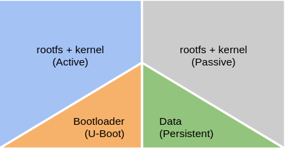
What we want is something as following… One rootfs partition (A) is active and executing, the other one (B) is used for the update. When a new updates arrives it goes into B, while rootfs in A is active. After reboot B becomes the active rootfs and A can be used for updates. If anything goes wrong during the update to B, we should still be able to load A because it was working fine for us previously. E voila, we got ourselves a dual rootfs with rollback mechanism.
For our embedded device the bootloader assures which rootfs (A or B) is loaded. The u-boot bootloader relies on environment variables to select which partition contains the rootfs of our Linux system. The rootfs partition is passed into the kernel as kernel argument. Swupdate has support for updating such u-boot environment variables from linux userspace, though it doesn’t offer a fully working dual rootfs with rollback mechanism by itself. The swupdate docs introduce a high level overview on how you could implement this yourself. But for anything bootloader related they refer to the u-boot docs. Before we dive into that, what you should do is making sure you have partitioned your device to include 2 root filesystems. I created following partitions on my target device:
/dev/mmcblk2 (emmc device, 16Gb)
/dev/mmcblk2p1: boot (fat32, 32Mb)
/dev/mmcblk2p2: rootfs1 (ext4, 2Gb)
/dev/mmcblk2p3: rootfs2 (ext4, 2Gb)
/dev/mmcblk2p4: data (ext4, 10Gb)
Next up is adding support in u-boot for changing the active rootfs partition. The bootcmd is executed by u-boot when going from bootloader stage to init kernel stage. U-boot also tells us on which device the kernel can find the rootfs. It’s passed as kernel argument using the bootargs variable. For example it could say:
bootargs root=/dev/mmcblk2p2 rdinit=/bin/kinit rw single
Editing this variables will make sure that the kernel looks for the rootfs in some other place. For example, when we use below modification the rootfs will be loaded from the third partition instead if the second:
bootargs root=/dev/mmcblk2p3 rdinit=/bin/kinit rw single
In this case it easier to store the rootfs partititon as a variable by itself so that when we update the bootargs we don’t discard any other modifications to it:
rootfspart 3

bootargs root=/dev/mmcblk2p${rootfspart} rdinit=/bin/kinit rw single
We can either alter the variable inside u-boot using the setenv command, or from Linux userspace using the fw_setenv tool provided by libubootenv (a binary compatible u-boot-fw-utils alternative). Swupdate will need to set the correct rootfs partition using fw_setenv after it has successfully deployed a rootfs update. Upon next boot, u-boot will pickup the updated variable and switch to the new rootfs.
However, when things go wrong and we’re unable to enter linux userspace using that new rootfs we want some system to detect these kind of errors. U-boot comes with bootcount and bootlimit support, but in many cases you still need to enable it before you can start using it. You need to add the support at compile time, in your u-boot source code you need to search the header file that adds support for your board. It’s found under the include/configs directory. Add:
CONFIG_BOOTCOUNT_LIMIT will add support for a bootcount variable. CONFIG_BOOTCOUNT_ENV makes sure that the bootcount variable is stored in the u-boot uenv so that after reboot tits value is not discarded. Each time the system is reset (not power cycled!) the bootcount variable increments and its updated value stored in the uenv. We can compare the bootcount to a bootlimit variable and use that to swap rootfs partitions. The actual comparison is already being taken care of in u-boot, you only need to setup the bootlimit variable (for example: setenv bootlimit 5) otherwise the bootcounter will be ignored by u-boot. If the bootlimit is reached, u-boot will run the altbootcmd instead of the usual bootcmd. Altbootcmd is by default not defined in u-boot, that you also have to do yourself. One use case is that altbootcmd can make sure that the rootfspart variable that I’ve introduced earlier is being swapped between 2 and 3, and next call the normal boot command (bootcmd). Another thing you need to take care of is that Linux userspace will also need to reset the persistently stored bootcount variable at each boot in order to prevent the bootlimit from being reached when our system is doing fine.
One more thing about the bootcount variable. The variable is write protected by another variable called upgrade_available. The latter, when not set, will prevent u-boot from actually writing the incremented bootcount variable to the u-boot environment. Hence, bootcount won’t increment as long as upgrade_available is unset. It’s introduced to prevent writing to the uenv at each boot thus lowering the wearing and reducing any issues that could occur due to power loss while writing. In linux userspace you should also check the upgrade_available variable first before resetting the bootcount.
In the end… what swupdate needs to do after it has deployed its artifacts is making sure that the upgrade_available variable is set which will enable the bootcounter upon next reboot. If all goes well the new rootfs will boot into linux and some script will unset the upgrade-available variable and reset the bootcount. However if things go wrong the bootcount will be increased and the system will reset until the bootlimit is reached. Now we will rollback into the working rootfs where we started the upgrade from. That same script will verify all is ok and unset the upgrade-available variable and reset the bootcount. The device should also notify to the end customer that the update failed. At next boot the device will keep booting into the “old” and stable rootfs. The user will have to reapply a new update after verifying why the previous update failed.
For all of this this to work we need to edit the CONFIG_EXTRA_ENV_SETTINGS statement in the u-boot sources. Its found in the same file where you set the CONFIG_BOOTCOUNT_LIMIT. Add following lines:
The modifications set the bootlimit to 5, and set the default routfs partition to 2. The altbootcmd makes sure we can switch partitions during rollback and the modified bootargs assures that the rootfs partition is loaded from an uenv variable.
Rollback in action
With that integrated in our bootloader we can start testing the rollback feature. Update your sdcard/emmc image and run it with your device. It should boot as always using the bootcmd variable, and load the rootfs in partition 2. At this stage, partition 3 is still empty. Once you’re in linux, check the uenv using fw_printenv. You should see the newly added bootcount and such vars. If it’s not the case, make sure to reset u-boot to its default variable values. Next we’re going to enable the bootcounter, so execute:
$ fw_setenv upgrade_available 1
Note that we haven’t implemented any script yet that resets the upgrade_available and bootcount variables. So by sending a reboot command we will see the bootcounter incrementing much alike in situations where a watchdog would kick in whenever loading the rootfs hangs. Now reboot the system from u-boot all the way up to linux and back using the reboot command, and repeat until the bootlimit is reached. At this point you’ll see some extra debug lines during the bootloader stage explaining that the altbootcmd is used:
Warning: Bootlimit (3) exceeded. Using altbootcmd.
Hit any key to stop autoboot: 0
Saving Environment to MMC...
Writing to MMC(0)... done
WARN: rollback RootFS to /dev/mmcblk2p3
Furthermore since partition 3 (/dev/mmcblk2p3) is still empty your linux should now also fail to boot due to missing rootfs. In the bootlog you’ll see a kernel panic:
Kernel panic - not syncing: VFS: Unable to mount root fs on unknown-block(179,10)
To overdue this you can easily go back into the u-boot shell and setting the rootfspart variable back to 2. Though, this is also a good moment to install a secundary rootfs in partition 3 to test if you can successfully start the updated rootfs. I’m not covering this, but I’m expecting you did that.
Preventing rollback in sunny-day scenarios
The next step is to make sure that, once your updated Linux os is up and running, you have a script executed that disables the bootcounter. It won’t go to much into detail here, but it could be as easily as having the underneath bash script executing through your init system of choice:
#!/bin/sh

# Always check if the upgrade_available var is set
# to reduce write cycles to the uenv.
ISUPGRADING=$(fw_printenv upgrade_available | awk -F'=' '{print $2}')
echo "upgrade_available=$ISUPGRADING"
if [ -z "$ISUPGRADING" ]
then
    echo "No RootFs update pending"
else
    echo "RootFs update pending, verifying system"
    # Perform extra checks here.
    # If anything went wrong, reboot again until the bootlimit is reached
    # which triggers a rollback of the RootFs
    fw_setenv upgrade_available
    fw_setenv bootcount 0
fi
You may have higher demands in verifying if the systems is running well such assuring that your application is running. Or maybe you want to assure that your internet connection is up, or that your device is able to notify the remote update server your os version and such. I leave that up to you…
Watching kernel panics
From what we noticed earlier, sometimes things go wrong and our rootfs fails to load, hence a kernel panic is triggered. For testing purposes you may also wipe one of your partitions: wipefs -a -t ext4 -f /dev/mmcblk2p3. It will trigger that same kernel panic we saw earlier. Unfortunately this will lock our device into a failed state and a manual reset will need to be performed. Sometimes that may be desirable, but in many cases you’ll want the show to go on. There are some ways to make the device autoreboot when such scenarios occur. Some may want to use a (external) watchdog to catch any errors from happening but I found that using the kernel’s panic reset system was a very easy way to get some sort of similar behavior. This kernel features makes sure that whenever a kernel panic occurs the system will be resetted. One way to set this up is feeding following kernel argument in u-boot:
panic=5
It will trigger a reset 5 seconds after a kernel panic occurred:
No filesystem could mount root, tried: ext3
ext2 ext4
vfat
Kernel panic - not syncing: VFS: Unable to mount root fs on unknown-block(179,10)
CPU0: stopping
CPU: 0 PID: 0 Comm: swapper/0 Not tainted 4.9.88-9512b3d443a53afbc8c7c18894249f78b62cc324+g9512b3d #1
...
Rebooting in 5 seconds..

U-Boot SPL 2017.03-c94efdc139f6a6c193aaf77f171a01d09686451c+gc94efdc (Jul 14 2020 - 09:46:33)
Integrating the u-boot environment in Swupdate
Then there also the swupdate manifest, or as they call it: the sw-description.
software =
{
    version = "2.3.0";

    mylinuxboard = {
        hardware-compatibility: [ "1.0" ];
        rootfs1: {
            images: (
                {
                    filename = "rootfs.ext4.gz";
                    compressed = "zlib";
                    installed-directly = true;
                    device = "/dev/mmcblk2p2";
                }
            );
            bootenv: (
                {
                    name = "rootfspart";
                    value = "2";
                },
                {
                    name = "upgrade_available";
                    value = "1";
                }
            );
            scripts: (
                {
                    filename = "resizeRootsfs.sh";
                    type = "postinstall";
                    data = "2"
                }
            );
        }
        rootfs2: {
            images: (
                {
                    filename = "rootfs.ext4.gz";
                    compressed = "zlib";
                    installed-directly = true;
                    device = "/dev/mmcblk2p3";
                }
            );
            bootenv: (
                {
                    name = "rootfspart";
                    value = "3";
                },
                {
                    name = "upgrade_available";
                    value = "1";
                }
            );
            scripts: (
                {
                    filename = "resizeRootsfs.sh";
                    type = "postinstall";
                    data = "3"
                }
            );
        }
    }
}
This describes the software infrastructure, and is a manifest used by swupdate to update parts of your system. In our case it defines that we have under our software collection stuff specially made for the “mylinuxboard” target which has revision “1.0”. It has 2 sub-collections that defines the updates for the rootfs’es on partition 2 and 3. The 2 sub-collections each contain an image part which handles the actually copying of the compressed rootfs into the target partition. And they also contain another part which describe the bootloader integration code to execute. On our case it defines the u-boot uenv code to update using the fw_setenv (more or less). So what we do here is not only making sure that the rootfs is deployed into the correct partition, we also enable the u-boot bootcounter (through upgrade_available) and set the target partition that we want to start using after reboot so that the newly updated rootfs is being used.
We can now create the update archive that contains the sw-desciption and all files that need to be deployed. From Yocto you can create a recipe to do that, but we can also do it from command line using following script:
#!/bin/bash

CONTAINER_VER="1.0.0"
PRODUCT_NAME="my-software"
FILES="sw-description \
    resizeRootsfs.sh \
    rootfs.ext4.gz \
"
for i in $FILES;do
    echo $i;done | cpio -ov -H crc > ${PRODUCT_NAME}_${CONTAINER_VER}.swu
We can now execute swupdate using the .swu archive we just created:
Swupdate v2019.11.0
Licensed under GPLv2. See source distribution for detailed copyright notices.
Running on mylinuxboard Revision 1.0
Registered handlers:
dummy
uboot
bootloader
flash
lua
raw
rawfile
rawcopy
shellscript
preinstall
postinstall
software set: mylinuxboard mode: rootfs2
[TRACE] : SWUPDATE running : [network_initializer] : Main loop Daemon
[TRACE] : SWUPDATE running : [extract_sw_description] : Found file:
filename sw-description
size 2018
checksum 0x1b90d VERIFIED
[TRACE] : SWUPDATE running : [listener_create] : creating socket at /tmp/sockinstctrl
[TRACE] : SWUPDATE running : [listener_create] : creating socket at /tmp/swupdateprog
[TRACE] : SWUPDATE running : [get_common_fields] : Version 2.3.0
[TRACE] : SWUPDATE running : [parse_hw_compatibility] : Accepted Hw Revision : 1.0
[TRACE] : SWUPDATE running : [parse_images] : Found compressed Image: rootfs.ext4.gz in device : /dev/mmcblk2p3 for handler raw
[TRACE] : SWUPDATE running : [parse_bootloader] : Bootloader var: upgrade_available = 1
[TRACE] : SWUPDATE running : [parse_bootloader] : Bootloader var: rootfspart = 3
[TRACE] : SWUPDATE running : [check_hw_compatibility] : Hardware mylinuxboard Revision: 1.0
[TRACE] : SWUPDATE running : [check_hw_compatibility] : Hardware compatibility verified
[TRACE] : SWUPDATE running : [cpio_scan] : Found file:
filename resizeRootsfs.sh
size 568
REQUIRED
[TRACE] : SWUPDATE running : [cpio_scan] : Found file:
filename rootfs.ext4.gz
size 239585335
REQUIRED
[TRACE] : SWUPDATE running : [install_single_image] : Fo mmcblk2: p1 p2 p3 p4
und installer for stream rootfs.ext4.gz raw
-----------------------
| RESIZING ROOTFS |
-----------------------
Using /dev/mmcblk2p2
e2fsck 1.43.5 (04-Aug-2017)
Pass 1: Checking inodes, blocks, and sizes
Pass 2: Checking directory structure
Pass 3: Checking directory connectivity
Pass 4: Checking reference counts
Pass 5: Checking group summary information
/dev/mmcblk2p2: 43400/304160 files (0.1% non-contiguous), 240702/304128 blocks
resize2fs 1.43.5 (04-Aug-2017)
Resizing the filesystem on /dev/mmcblk2p2 to 524288 (4k) blocks.
The filesystem on /dev/mmcblk2p2 is now 524288 (4k) blocks long.

[TRACE] : SWUPDATE running : [execute_shell_script] : Calling shell script /tmp/scripts/resizeRootsfs.sh 2: return with 0
Software updated successfully
Please reboot the device to start the new software
[INFO ] : SWUPDATE successful !
mmcblk2: p1 p2 p3 p4
Making it more robust
The above solution is a great start for most projects. However if you want to make it robust and production proof there are some more things that you could do:
Don’t store the u-boot bootcounter in the u-boot env. U-boot also supports storing in RAM, RTC, etc. It reduces write cycles but more importantly its a safer way of updating the bootcounter when a power loss occurs.
Use a dual u-boot-environment. If you have only one, a power strike during updating the uenv could have catastrophic results.
Have a dual boot partition. It will allow you to safely update your dtb and kernel in the same manner as the rootfs is updated.
Sign your artifacts. It assures that the distributor of the updates can be trusted, so that we can take for granted the fact that our update server is our own server and not someone else his.
Setup a watchdog that resets the device whenever boot issues occur, for example loading the rootfs not found.
Secure your firmware storage server so that your firmwares can only be downloaded by your software and no one else
Although I’ve missed most of the hype around the original Doom game back in the 90’s, I did get to play it at a friends place. But it was only until I started programming that I picked it up again after reading Master’s of Doom.
When I started working on a embedded Linux device last year based on the i.MX6 processor the idea began to grow to compile Doom for our custom Linux based OS as some sort of easter egg. Unfortunately the world is real and deadlines are always too short and I had to let go of this idea. More recently however some of our dev-boards had to be archived and so I took this opportunity to take one home for a short period of time and finally get this one settled for once and for all.
One way to get it working is to setup a cross-compilation toolchain and cross-compile one of the many source ports of the doom engine. Another way would be to properly integrate it with the build of our custom Linux OS. Since we’re using Yocto to build our image the idea was to create a separate meta-layer that includes everything you need. You can find the meta-layer at github/geoffrey-vl/meta-doom.
Initially I started integrating the prboom engine. I found out that the out-of-three build wasn’t working so well and I’ve bumped into some other issues’s as well. I had more luck using chocolate-doom which is better maintained. Chocolate-doom only recently switched over to using the SDL2 library so to be on the safe side I went to the latest version that runs on SDL(1). The game engine also requires libsdl-net which is currently not available in the official yocto repo’s. Luck was on my side when I bumped into a working libsdl-net recipe through google-search.
With the engine compiling happily I stumbled upon licensing issues. You have to own the game (and its game aka WAD files), so I couldn’t distribute anything that would be playable unless the user would copy its WAD files to our embedded system. Luckily there is the Freedoom project, a open-source implementation of the doom game. I also found a working recipe for Freedoom and so moments later my workstation produced a ready-to-play open-source implementation of the immensely populair Doom game.
Just for the kicks I also loaded my own WAD files, here is the result:
I noticed on the first yocto image that I've made there were some issue's regarding the wireless connection. I was not sure exactly what went wrong, but it seemed to be a kernel/driver issue. The rtl8192cu wifi interface had connection problems whenever I disconnected the eth0 interface. I din't find a lot of clue's except from some folks complaining about the 8192cu kernel module not really working out to well. Through lsmod I found out that I was using this module. When using the adapter on my Ubuntu machine I noticed other drivers and modules got loaded - not the pesky 8192cu module - and the wireless interface was indeed working out well.
First idea would be to swap kernel modules by reconfiguring the kernel config in Yocto. However, since I'm recompiling I might as well pull in the latest sources for my working branch and just recompile the entire image. As a result I'd upgrade from Linux 4.4 to 4.9.
I also wrapped some of my work into script so that updating another time later on would make life much easier. Here is what I did:
Updating yocto to latest sources
The script below will pull in all latest meta-layers from the morty branch. Although newer branches are available like pyro and rocko, I'm not yet thinking about pulling these in since this will have a bigger impact on the package versions. Here is the script:
Again, save it to the same directoy, make it executable and run it (overnight).
Deploy the image to SD card
Jumpnowtek already provided some tools to automate some of the task that need to be done to get all your binaries on a SD card. The following script just wraps some of these tools for convenience:
#!/bin/bash
echo "##############################################"
echo "# Choose your SD card                        #"
echo "##############################################"
lsblk -dn -o NAME,SIZE
while true; do
	echo "# Device to format: "
	read SDCARD
	echo "selected: $SDCARD"
	if lsblk -dn -o NAME | grep "$SDCARD"; then

		break;
	else
		echo "Device not supported... retry"
	fi
done
echo "##############################################"
echo "# using card [$SDCARD]"
echo "##############################################"
echo ""
echo "##############################################"
echo "# making preparations                        #"
echo "##############################################"
MOUNTDIR="/media/card"
if [ ! -d "$MOUNTDIR" ]; then
	echo "Creating directory $MOUNTDIR"
	sudo mkdir "$MOUNTDIR"
else
	echo "Using $MOUNTDIR"
	umount "/media/card"
fi

echo "exporting variables"
export OETMP=/media/geoffrey/Data/yocto-pi/rpi/build/tmp
export MACHINE=raspberrypi2

echo "unmounting stuff"
PART1="/dev/$SDCARD""p1"
PART2="/dev/$SDCARD""p2"
umount $PART1
umount $PART2

echo "##############################################"
echo "# copy boot partition                        #"
echo "##############################################"
./rpi/meta-rpi/scripts/copy_boot.sh $SDCARD

echo "##############################################"
echo "# copy boot partition                        #"
echo "##############################################"
IMAGENAME="qt5"
HOSTNME="thermopi2"
./rpi/meta-rpi/scripts/copy_rootfs.sh $SDCARD $IMAGENAME $HOSTNME
Once again, save the script and run it.
Boot the new system
With the system back up you first may want to check if you get the wlan0 interface working this time. But let's check the kernel version and driver modules first:
We notice the newer 4.9 kernel is in use, and furthermore we also see the rtl8192cu and some other related modules loaded just as I saw on my Ubuntu machine. I went ahead and configured wlan again as mentioned earlier, é voila problem solved!
Deploying custom software
I'm not yet about to open source the entire codebase for my thermostat, I think there's already lots of stuff here to get you going. I also haven't yet made a decicated recipe in Yocto included my own made binaries. For now I will deploy my thermostat software by hand and create a little init script so that it gets loaded automatically at system boot.
For starters create the init script with following content:
We turned our software into a service that can be started through the init daemon by executing the start and stop commands. One last step is need to be made for the service to automatically start at boot: we must link it to runlevel 5 so that the init service picks it up when going through all services connected to the runlevel.
root@thermopi2:/etc/rc5.d# ls -al
total 8
drwxr-xr-x  2 root root 4096 Nov  5 23:41 .
drwxr-xr-x 35 root root 4096 Nov  7 21:12 ..
lrwxrwxrwx  1 root root   20 Nov  5 23:41 S01networking -> ../init.d/networking
lrwxrwxrwx  1 root root   16 Nov  5 23:40 S02dbus-1 -> ../init.d/dbus-1
lrwxrwxrwx  1 root root   14 Nov  5 23:41 S09sshd -> ../init.d/sshd
lrwxrwxrwx  1 root root   21 Nov  5 19:46 S15mountnfs.sh -> ../init.d/mountnfs.sh
lrwxrwxrwx  1 root root   28 Nov  5 23:41 S15pi-blaster.boot.sh -> ../init.d/pi-blaster.boot.sh
lrwxrwxrwx  1 root root   14 Nov  5 23:41 S20ntpd -> ../init.d/ntpd
lrwxrwxrwx  1 root root   18 Nov  5 23:41 S20samba.sh -> ../init.d/samba.sh
lrwxrwxrwx  1 root root   16 Nov  5 23:40 S20syslog -> ../init.d/syslog
lrwxrwxrwx  1 root root   22 Nov  5 19:46 S99rmnologin.sh -> ../init.d/rmnologin.sh
lrwxrwxrwx  1 root root   23 Nov  5 20:56 S99stop-bootlogd -> ../init.d/stop-bootlogd
root@thermopi2:/etc/rc5.d# ln -s ../init.d/quicktemp.sh S95quicktemp
root@thermopi2:/etc/rc5.d# ls -al
total 8
drwxr-xr-x  2 root root 4096 Nov  7 23:29 .
drwxr-xr-x 35 root root 4096 Nov  7 21:12 ..
lrwxrwxrwx  1 root root   20 Nov  5 23:41 S01networking -> ../init.d/networking
lrwxrwxrwx  1 root root   16 Nov  5 23:40 S02dbus-1 -> ../init.d/dbus-1
lrwxrwxrwx  1 root root   14 Nov  5 23:41 S09sshd -> ../init.d/sshd
lrwxrwxrwx  1 root root   21 Nov  5 19:46 S15mountnfs.sh -> ../init.d/mountnfs.sh
lrwxrwxrwx  1 root root   28 Nov  5 23:41 S15pi-blaster.boot.sh -> ../init.d/pi-blaster.boot.sh
lrwxrwxrwx  1 root root   14 Nov  5 23:41 S20ntpd -> ../init.d/ntpd
lrwxrwxrwx  1 root root   18 Nov  5 23:41 S20samba.sh -> ../init.d/samba.sh
lrwxrwxrwx  1 root root   16 Nov  5 23:40 S20syslog -> ../init.d/syslog
lrwxrwxrwx  1 root root   22 Nov  7 23:29 S95quicktemp -> ../init.d/quicktemp.sh
lrwxrwxrwx  1 root root   22 Nov  5 19:46 S99rmnologin.sh -> ../init.d/rmnologin.sh
lrwxrwxrwx  1 root root   23 Nov  5 20:56 S99stop-bootlogd -> ../init.d/stop-bootlogd
Reboot the pi, you'll now see that your software is auto loaded at boot!
Extending the SD card lifetime
As I've mentioned in other blog post having your logs written to a tempfs volatile file system (in RAM) extends the SD card life time a lot. I wont go into detail again here, just have a look here. Note that in our Yocto image there is already the tmpfs created for you so actually we don't have to do anything extra here.
Edit
Although the RTL8192CU driver brought some improvements, it didn't offer a permanent solution. To fix it I've blacklisted the driver again:
The Supervisor daemon is an easy to use utility which makes sure your services are running and never stop. It has its own logging infrastructure which you can check when things go wrong, aside of your own logging infrastructure. However, logging can degrade the SD card on embedded Raspberry Pi systems. Tmpfs to the resque!
Tmpfs allows us to make a filesystem in RAM so that no write cycli is made on the SD card. It can easily be made be editing /etc/fstab:
When you reboot your system the content of /var/log, where all log messages are usually found, is now stored on the RAM based filesystem, hence improving SD card lifetime.
Enter Supervisor. To install supervisor:
sudo apt-get install supervisor
Configure your service by editing /etc/supervisor/conf.d/, for example I have a service running in Mono so I edit /etc/supervisor/conf.d/shutterservice.conf. Inside you’ll find following content:
When you reboot your system again you’ll find that your service might not be available. You can verify this be starting and stopping the service by hand using supervisorctl. This tool will generate some obscure errors at this stage.
The problem here is that the supervisor daemon was not able to create its /var/log/supervisor logging directory when the system boots. You may create the directory yourself and restart supervisor manually using:
sudo mkdir /var/log/supervisor
sudo service supervisor restart
This time supervisor should be able to start, double check the logging files to make sure. However when you reboot your Pi again the tmpfs system will be cleared again, and once again supervisor will not be able to start automatically because of the missing log folder. We can fix this by using a config file for systemd which automatically creates temporary files.
Go ahead and create this config file:
sudo vim /etc/tmpfiles.d/supervisor.conf
Enter following content:
d /var/log/supervisor 0777 root root
When you reboot your system everything should be working as expected, plus you have just extended your SD card’s lifetime!
Previously we made ourselves a Linux distribution ourselves for our target embedded system. We included basic Qt5 support which allows us to create a fast and responsive C++ frontend. This time we will further develop our embedded system and prepare it for usage.
Adding QtQuick – QML support
In the previous article we succeeded in created a QtWidget based application. However, with QtQuick there is a new UI framework available which has its own set of benefits. You may already have noticed that QtCreator comes with lots of examples and you may have even tried some of them. However, if you (like me) created your Yocto based OS using the bitbake qt5-basic-image command you will find that some programs may not work when yo run them on your embedded device:
root@raspberryyocto:~# ./clocks
./clocks: error while loading shared libraries: libQt5Quick.so.5: cannot open shared object file: No such file or directory
root@raspberryyocto:~#
Basically we didn’t include support for QtQuick when we compiled our OS. So if you’re into using QtQuick go back through your Yocto working folder and bitbake the qt5-image:
Notice how fast compiling the image goes this time compared to when we build the qt5-basic-image. The reason for this faster build time is because the qt5-image inherits the qt5-basic-image and Yocto just needed to recompile some of the components that were not yet compiled. Also note that you don’t need a new SDK and you shouldn’t need to re-configure QtCreator.
With your SD card already formatted you only need to copy the compiled files to your SD card:
geoffrey@geoffrey-Dell-XPS-L502X:/media/geoffrey/Data/yocto-pi/rpi/build$ cd ../meta-rpi/scripts/
geoffrey@geoffrey-Dell-XPS-L502X:/media/geoffrey/Data/yocto-pi/rpi/meta-rpi/scripts$ sudo umount /dev/mmcblk0p1
geoffrey@geoffrey-Dell-XPS-L502X:/media/geoffrey/Data/yocto-pi/rpi/meta-rpi/scripts$ sudo umount /dev/mmcblk0p2
geoffrey@geoffrey-Dell-XPS-L502X:/media/geoffrey/Data/yocto-pi/rpi/meta-rpi/scripts$ export MACHINE=raspberrypi
geoffrey@geoffrey-Dell-XPS-L502X:/media/geoffrey/Data/yocto-pi/rpi/meta-rpi/scripts$ export OETMP=/media/geoffrey/Data/yocto-pi/rpi/build/tmp
geoffrey@geoffrey-Dell-XPS-L502X:/media/geoffrey/Data/yocto-pi/rpi/meta-rpi/scripts$ ./copy_rootfs.sh mmcblk0 qt5 raspberryyocto

OETMP: /media/geoffrey/Data/yocto-pi/rpi/build/tmp
IMAGE: qt5
HOSTNAME: raspberryyocto

File found: /media/geoffrey/Data/yocto-pi/rpi/build/tmp/deploy/images/raspberrypi/qt5-image-raspberrypi.tar.xz

Block device not found: /dev/mmcblk02, trying p2

Formatting /dev/mmcblk0p2 as ext4
[sudo] wachtwoord voor geoffrey:
/dev/mmcblk0p2 bevat een ext4-bestandssysteem met label 'ROOT'
laatst aangekoppeld op / op Sun Feb 19 22:07:51 2017
Toch doorgaan? (j,n) j
Mounting /dev/mmcblk0p2
Extracting qt5-image-raspberrypi.tar.xz to /media/card
Writing raspberryyocto to /etc/hostname
Unmounting /dev/mmcblk0p2
Done
geoffrey@geoffrey-Dell-XPS-L502X:/media/geoffrey/Data/yocto-pi/rpi/meta-rpi/scripts$
With that done we need to have a QtQuick test application. If you haven’t yet tried on of the QtCreator’s QtQuick examples do so now. Get back to your embedded device, insert the SD card and boot. Once booted, retrieve the device’s IP address and copy over any QtQuick test application. I’ve used the clocks application. Once you have the application compiled and copied over to the raspberry pi, ssh into your pi and start the application (or launch it from within QtCreator if you’ve had it still openened). You should see more or less something like this:
If you happen to run into “out of memory” errors:
root@raspberryyocto:~# ./clocks
QML debugging is enabled. Only use this in a safe environment.
Unable to query physical screen size, defaulting to 100 dpi.
To override, set QT_QPA_EGLFS_PHYSICAL_WIDTH and QT_QPA_EGLFS_PHYSICAL_HEIGHT (in millimeters).
JIT is disabled for QML. Property bindings and animations will be very slow. Visit https://wiki.qt.io/V4 to learn about possible solutions for your platform.
glGetError 0x505
QSGTextureAtlas: texture atlas allocation failed, out of memory
… then you should tweak the CPU/GPU memory allocation settings. This settings is loaded at boot and it is also saved in a config file on your boot partition. To adjust the config file we first need to mount the boot partition, and next we can edit the file using the vi editor:
root@raspberryyocto:~# mkdir /mnt/fat
root@raspberryyocto:~# mount /dev/mmcblk0p1 /mnt/fat
root@raspberryyocto:~# vi /mnt/fat/config.txt
Add gpu_mem=256 to this file and reboot your pi. Try again running the clocks application, things should go now as intended:
root@raspberryyocto:~# ./clocks
QML debugging is enabled. Only use this in a safe environment.
Unable to query physical screen size, defaulting to 100 dpi.
To override, set QT_QPA_EGLFS_PHYSICAL_WIDTH and QT_QPA_EGLFS_PHYSICAL_HEIGHT (in millimeters).
JIT is disabled for QML. Property bindings and animations will be very slow. Visit https://wiki.qt.io/V4 to learn about possible solutions for your platform.
Setting the timezone
To show the current time we will rely on NTP. RaspberryPi does not come with a RTC see I don’t see any other option. NTP is already added via Yocto, we only have to set the correct timezone:
root@yoctopi:~# ls -l /etc/localtime
lrwxrwxrwx 1 root root 27 Apr 10 18:36 /etc/localtime -> /usr/share/zoneinfo/EST5EDT
root@yoctopi:~# rm /etc/localtime
root@yoctopi:~# ln -s /usr/share/zoneinfo/Europe/Paris /etc/localtime
root@yoctopi:~# date
Sun Apr 16 12:30:40 CEST 2017
Adding a touch screen
The RaspberryPi community has a very decent 7″ touch screen. There is not much to say about, I got one, followed the instructions to hook it op and basically started testing some my applications straight away!
Side note: I used the same housing as show above. This one has the display upside down, the rotate the display through software we must again edit the config file on the boot partition:
root@raspberryyocto:~# mkdir /mnt/fat
root@raspberryyocto:~# mount /dev/mmcblk0p1 /mnt/fat
root@raspberryyocto:~# vi /mnt/fat/config.txt
and add:
display_rotate=2
Restart to apply your changes.
Adding a HTU21D I²C temperature sensor
The HTU21D is a decent temperature and humidity sensor which perfectly suits our needs. To hook it up to our Raspberry Pi 2:
Before we can use the I2C bus we must again edit the Pi’s config file:
root@raspberryyocto:~# mkdir /mnt/fat
root@raspberryyocto:~# mount /dev/mmcblk0p1 /mnt/fat
root@raspberryyocto:~# vi /mnt/fat/config.txt
and add:
dtparam=i2c_arm=on
Restart to apply your changes.
After the system has booted into Linux again we will first check if the i2c_bcm2708 module has been loaded:
This write-up will focus on how to create your own Linux distribution, using Yocto. Yocto is a popular tools these days for creating an embedded operating system from scratch. I’m not going to talk you into how Yocto works, where it came from and so on. If you have no idea at all then go visit the Yocto Project website.
Because this is going to be a single unit creation you might think that it is a bit silly to go through the entire phase of creating you own Linux distribution. Well, off course that’s true, using a full blown distribution like Debian, Fedora or Ubuntu might have the benefits of having the distribution already created for you, with every tool available that you’ll ever need. Creating a Yocto based distribution also has some benefits of its own. For example you can add or remove system components and use only those you really need. This may for example reduce boot time. Furthermore, you have more control over your system, you can toss in/out the components that you require and so the OS isn’t bloated either with programs and tools that you’d never use. This may gratefully reduce the OS’s footprint. And actually it’s a good training to get to know the Yocto Project because it is often used nowadays in embedded systems. At least if that’s where you’re interested in.
The embedded device I’m about to use is the Raspberry Pi 2. The reason I’m choosing this device is simple: it has all the components that I need, it has support for many add-ons, it has a large community which may help you out whenever you get into trouble, it’s relatively cheap to buy and easy to find in stores, and I have already sitting one on my desk waiting for an application to be used in.
(Bit)baking your own Linux distribution
I could go through all the steps of how to create a Yocto based distribution for your Raspberry Pi. Fact is that someone already did write a very good tutorial which I’ve couldn’t done better, so first head over to the Jumpnowtek website and follow the tutorial. Furthermore this guy already did a lot of work for you so his using his layer for raspberry pi will add support for many devices. You can find his Git repo here. For those who’re not fund on compiling their own Yocto distribution but instead just want to go ahead and use it, you can also find downloadable content on the Jumpnowtek download sector.
For my Yocto project I’ve used my Dell XPS 15 laptop with a second HDD of 512Gb installed, 8Gb of RAM and the Ubuntu 16.04 LTS operating system. Because I had this drive already available I’m using this one, but if you’re about to buy a new build setup look for something which is fast, which has a CPU with many cores, which contains a lot of DRAM, and something that uses a SDD. Using faster build systems might dramatically reduce build times because building your own distribution on a system of few years old might easily take 6 to 8 hours!
I creating a dedicated directory (/media/geoffrey/Data/yocto-pi) on my second hard drive and I’ll use this directory to make all of my yocto builds. First pull-in all required repos as instructed on the Jumpnowtek website and initialize your build directory. Because I’m going to be using the Qt5 framework (a C++ UI framework) I’ll be building a QT5 Yocto image and so I need to include several QT5 layers. Here is my bblayers.conf file:
I’ve build the Yocto image using following command:
geoffrey@geoffrey-Dell-XPS-L502X:/media/geoffrey/Data/yocto-pi$ source poky-morty/oe-init-build-env /media/geoffrey/Data/yocto-pi/rpi/build

## Shell environment set up for builds. ###

You can now run 'bitbake '

Common targets are:
 core-image-minimal
 core-image-sato
 meta-toolchain
 meta-toolchain-sdk
 adt-installer
 meta-ide-support

You can also run generated qemu images with a command like 'runqemu qemux86'

geoffrey@geoffrey-Dell-XPS-L502X:/media/geoffrey/Data/yocto-pi/rpi/build$
geoffrey@geoffrey-Dell-XPS-L502X:/media/geoffrey/Data/yocto-pi/rpi/build$ bitbake qt5-basic-image
Wait for the build to complete and next copy your files to the SD card using the Jumpnowtek site’s instructions. Make sure you copy it to the correct disk!
geoffrey@geoffrey-Dell-XPS-L502X:/media/geoffrey/Data/yocto-pi/rpi/meta-rpi/scripts$ lsblk
NAME MAJ:MIN RM SIZE RO TYPE MOUNTPOINT
sda 8:0 0 465,8G 0 disk
├─sda1 8:1 0 244,8G 0 part /
├─sda2 8:2 0 220,6G 0 part
└─sda3 8:3 0 450M 0 part
sdc 8:32 1 3,7G 0 disk
├─sdc1 8:33 1 64M 0 part
└─sdc2 8:34 1 3,6G 0 part

geoffrey@geoffrey-Dell-XPS-L502X:/media/geoffrey/Data/yocto-pi/rpi/meta-rpi/scripts$ sudo mkdir /media/card
geoffrey@geoffrey-Dell-XPS-L502X:/media/geoffrey/Data/yocto-pi/rpi/meta-rpi/scripts$ sudo ./mk2parts.sh sdc
[sudo] wachtwoord voor geoffrey:

Working on /dev/sdc

umount: /dev/sdc: not mounted
DISK SIZE – 3963617280 bytes

Okay, here we go ...

=== Zeroing the MBR ===

1024+0 records gelezen
1024+0 records geschreven
1048576 bytes (1,0 MB, 1,0 MiB) copied, 0,53551 s, 2,0 MB/s

=== Creating 2 partitions ===

Checking that no-one is using this disk right now ... OK

Disk /dev/sdc: 3,7 GiB, 3963617280 bytes, 7741440 sectors
Units: sectors of 1 * 512 = 512 bytes
Sector size (logical/physical): 512 bytes / 512 bytes
I/O size (minimum/optimal): 512 bytes / 512 bytes

>>> Created a new DOS disklabel with disk identifier 0x6efbfa0c.
Created a new partition 1 of type 'W95 FAT32 (LBA)' and of size 64 MiB.
/dev/sdc2: Created a new partition 2 of type 'Linux' and of size 3,6 GiB.
/dev/sdc3:
New situation:

Apparaat Op. Start Einde Sectoren Size Id Type
/dev/sdc1 * 8192 139263 131072 64M c W95 FAT32 (LBA)
/dev/sdc2 139264 7741439 7602176 3,6G 83 Linux

The partition table has been altered.
Calling ioctl() to re-read partition table.
Syncing disks.

=== Done! ===

geoffrey@geoffrey-Dell-XPS-L502X:/media/geoffrey/Data/yocto-pi/rpi/meta-rpi/scripts$ lsblk
NAME MAJ:MIN RM SIZE RO TYPE MOUNTPOINT
sda 8:0 0 465,8G 0 disk
├─sda1 8:1 0 244,8G 0 part /
├─sda2 8:2 0 220,6G 0 part
└─sda3 8:3 0 450M 0 part
sdc 8:32 1 3,7G 0 disk
├─sdc1 8:33 1 64M 0 part
└─sdc2 8:34 1 3,6G 0 part
geoffrey@geoffrey-Dell-XPS-L502X:/media/geoffrey/Data/yocto-pi/rpi/meta-rpi/scripts$ export OETMP=/media/geoffrey/Data/yocto-pi/rpi/build/tmp
geoffrey@geoffrey-Dell-XPS-L502X:/media/geoffrey/Data/yocto-pi/rpi/meta-rpi/scripts$ export MACHINE=raspberrypi
geoffrey@geoffrey-Dell-XPS-L502X:/media/geoffrey/Data/yocto-pi/rpi/meta-rpi/scripts$ ./copy_boot.sh sdc
geoffrey@geoffrey-Dell-XPS-L502X:/media/geoffrey/Data/yocto-pi/rpi/meta-rpi/scripts$ ./copy_rootfs.sh sdc qt5 raspberryyocto

OETMP: /media/geoffrey/Data/yocto-pi/rpi/build/tmp
IMAGE: qt5
HOSTNAME: raspberryyocto

Formatting /dev/sdc2 as ext4
[sudo] wachtwoord voor geoffrey:
/dev/sdc2 bevat een ext4-bestandssysteem met label 'ROOT'
 laatst aangekoppeld op /media/card op Wed Mar 29 11:33:06 2017
Toch doorgaan? (j,n) j
Mounting /dev/sdc2
Extracting qt5-image-raspberrypi.tar.xz to /media/card
Writing raspberryyocto /etc/hostname
Unmounting /dev/sdc2
Done
Creating a cross-platform toolchain for application development
Even though our embedded device might contain all the tools needed to compile native applications, most of the time you’ll be wanting to use the processing power of your development machine to speed up development. For this reason we need to install the cross-compilation toolchain. But first we need to create the toolchain using bitbake. Navigate to your working directory and use following command to build the toolchain:
geoffrey@geoffrey-Dell-XPS-L502X:/media/geoffrey/Data/yocto-pi$ source poky-morty/oe-init-build-env /media/geoffrey/Data/yocto-pi/rpi/build

### Shell environment set up for builds. ###

You can now run 'bitbake '

Common targets are:
 core-image-minimal
 core-image-sato
 meta-toolchain
 meta-ide-support

You can also run generated qemu images with a command like 'runqemu qemux86'
geoffrey@geoffrey-Dell-XPS-L502X:/media/geoffrey/Data/yocto-pi/rpi/build$ clear; bitbake meta-toolchain-qt5
Loading cache: 100% |##################################################################| Time: 0:00:00
Loaded 2660 entries from dependency cache.
Parsing recipes: 100% |################################################################| Time: 0:00:01
Parsing of 1972 .bb files complete (1964 cached, 8 parsed). 2668 targets, 353 skipped, 0 masked, 0 errors.
NOTE: Resolving any missing task queue dependencies

Build Configuration:
BB_VERSION = "1.32.0"
BUILD_SYS = "x86_64-linux"
NATIVELSBSTRING = "universal"
TARGET_SYS = "arm-poky-linux-gnueabi"
MACHINE = "raspberrypi"
DISTRO = "poky"
DISTRO_VERSION = "2.2.1"
TUNE_FEATURES = "arm armv6 vfp arm1176jzfs callconvention-hard"
TARGET_FPU = "hard"
meta
meta-poky = "morty:a3fa5ce87619e81d7acfa43340dd18d8f2b2d7dc"
meta-oe
meta-multimedia
meta-networking
meta-python = "morty:1efa5d623bc64659b57389e50be2568b1355d5f7"
meta-qt5 = "morty:9aa870eecf6dc7a87678393bd55b97e21033ab48"
meta-raspberrypi = "master:e1f69daa805cb02ddd123ae2d4d48035cb5b41d0"
meta-rpi = "morty:03841471ccaed549a2a14a896c13f71af76cf482"

Initialising tasks: 100% |#############################################################| Time: 0:00:05
NOTE: Executing SetScene Tasks
NOTE: Executing RunQueue Tasks
NOTE: Tasks Summary: Attempted 3170 tasks of which 1605 didn't need to be rerun and all succeeded.
geoffrey@geoffrey-Dell-XPS-L502X:/media/geoffrey/Data/yocto-pi/rpi/build$
Again, this will take a lot of time, depending on how fast your dev-pc is. When the build completes you’ll get as a result the script that install the SDK on your development pc. On my pc it was found in the /media/geoffrey/Data/yocto-pi/rpi/build/tmp/deploy/sdk folder. The script is named poky-glibc-x86_64-meta-toolchain-qt5-arm1176jzfshf-vfp-toolchain-2.2.1.sh.
Run the script, and when asked for the install folder I’ve chosen the default option. If you plan to create more than one SDK I’d highly recommend to install each in their own directory. There is no need to run this script as root user. Note that running this script takes roughly 2 minutes to complete, enough time to grab a dieet coke!
geoffrey@geoffrey-Dell-XPS-L502X:/media/geoffrey/Data/yocto-pi/rpi/build/tmp/deploy/sdk$ ./poky-glibc-x86_64-meta-toolchain-qt5-arm1176jzfshf-vfp-toolchain-2.2.
1.sh
Poky (Yocto Project Reference Distro) SDK installer version 2.2.1
=================================================================
Enter target directory for SDK (default: /opt/poky/2.2.1):
You are about to install the SDK to "/opt/poky/2.2.1". Proceed[Y/n]? Y
[sudo] password for geoffrey:
Extracting SDK............................................................................................................................done
Setting it up...done
SDK has been successfully set up and is ready to be used.
Each time you wish to use the SDK in a new shell session, you need to source the environment setup script e.g.
 $ . /opt/poky/2.2.1/environment-setup-arm1176jzfshf-vfp-poky-linux-gnueabi
geoffrey@geoffrey-Dell-XPS-L502X:/media/geoffrey/Data/yocto-pi/rpi/build/tmp/deploy/sdk$
Compiling your first program
We came as far as creating a self-made Yocto based distribution with Qt5.7 pre-installed, plus having all the tools installed on our development pc to create a nice embedded application. If you don’t use an IDE then go ahead and use the instructions on the Jumpnowtek website to go ahead and compile your application using qmake.
qmake: could not exec '/usr/lib/x86_64-linux-gnu/qt4/bin/qmake': No such file or directory
… you probable forget to use the source command! Note that the source command is bound to the shell where you used it. If you used it inside a shell script than it will only take effect to the commands inside the shell script!
After compiling has completed you get several files as output. One of the files is the binary executable that represent our program. We can also verify if is has been compiled for ARM:
geoffrey@geoffrey-Dell-XPS-L502X:~/Qt5.5.1/Projects/HelloQtWidgets$ ls -l HelloQtWidgets
-rwxrwxr-x 1 geoffrey geoffrey 1181132 feb 18 17:33 HelloQtWidgets
geoffrey@geoffrey-Dell-XPS-L502X:~/Qt5.5.1/Projects/HelloQtWidgets$ ^C
geoffrey@geoffrey-Dell-XPS-L502X:~/Qt5.5.1/Projects/HelloQtWidgets$ file HelloQtWidgets
HelloQtWidgets: ELF 32-bit LSB executable, ARM, EABI5 version 1 (GNU/Linux), dynamically linked, interpreter /lib/ld-linux-armhf.so.3, for GNU/Linux 3.2.0, BuildID[sha1]=56d390438db87a396f5f28e7adbbdd69cdd0ee68, not stripped
We can now copy the file over to our embedded system:
Next, login to the embedded system using ssh and execute the binary file. You’ll need to have a display attached to your pi in order to view the UI:
geoffrey@geoffrey-Dell-XPS-L502X:~$ ssh [email protected]
root@raspberryyocto:~# ls
HelloQtWidgets
root@raspberryyocto:~# ./HelloQtWidgets
Unable to query physical screen size, defaulting to 100 dpi.
To override, set QT_QPA_EGLFS_PHYSICAL_WIDTH and QT_QPA_EGLFS_PHYSICAL_HEIGHT (in millimeters).
Setting up QtCreator
Whenever you’re about to create a more advanced program with an UI you’ll find yourselve in the need of a IDE. QtCreator is quit good in providing all the tools you need to create graphical applications so I highly recommend using QtCreator to develop your applications. We’ll now configure QtCreator to use the SDK we’ve used above.
First you need to install QtCreator. Go to the Qt website, fill in the licence form and download Qt5.7. You may also look for the open source version of Qt here. Next make the downloaded file executable and run it. You may install Qt in the default folder. Next we’ll configure QtCreator to use the compiler, debugger, etc. Note that for compiling native applications for our embedded system we need to source the SDK folder each time we run QtCreator. For convenience I created a script that does this for me:
geoffrey@geoffrey-Dell-XPS-L502X:~$ vim qtcreator4pi.sh
You should now see the default welcome page for QtCreator. Next from the main menu bar at the top of the application click the Tools menu item and open the Options window. Now do following steps (note that some steps might look a bit different as the screenshots I’ve made are made on a Qt5.5 setup):
Create your device
Navigate to Devices, click Add, select Generic Linux Device and start the Wizard. Enter following content:
Name: [pick your own name, for example Pi One]
Hostname: [the IP address of your raspberry pi]
Username: root
Authentication type: Password
Password: [leave empty]
Click next, QtCreator will now test your connection and if all goes well you’d get following output:
Connecting to host...

Checking kernel version...

Linux 4.4.43 armv6l

Checking if specified ports are available...

All specified ports are available.

Device test finished successfully.
Make sure to Apply your configuration at this point.
Configure the Qt Version
Navigate to Build &Run > Qt Versions, click Add. If not already selected, navigate and select the /opt/poky/2.2.1/sysroots/x86_64-pokysdk-linux/usr/bin/qt5/qmake executable. Adjust the path to your needs.
Configure the compiler
Navigate to Build & Run > Compilers, click Add, select GCC and use following settings:
Name: [choose your own name, for example Pi One GCC]
Compiler Path: /opt/poky/2.2.1/sysroots/x86_64-pokysdk-linux/usr/bin/arm-poky-linux-gnueabi/arm-poky-linux-gnueabi-g++
Configure the debugger
Navigate to Build & Run > Debuggers, click Add and use following settings:
Name: [choose your own name, for example Pi One GDB]
Path: /opt/poky/2.2.1/sysroots/x86_64-pokysdk-linux/usr/bin/arm-poky-linux-gnueabi/arm-poky-linux-gnueabi-gdb
Configure the kit (aka hook everything up together)
Navigate to Build & Run > Kits, click Add, and enter following content.
Name: [choose your own name, for example Pi One]
Device Type: Generic Linux Device
Device: [choose the device we created earlier]
Sysroot: /opt/poky/2.2.1/sysroots/arm1176jzfshf-vfp-poky-linux-gnueabi
Compiler: [choose the compiler we configured earlier]
Debugger: [choose the debugger we configured earlier]
Qt Version: [choose the Qt version we configured earlier]
Qt mkspec: linux-oe-g++
We’ve now correctly configured QtCreator for cross-platform development. We need to perform this configuration only once per SDK. Note that whenever you’re going to compile, deploy or debug your application on your embedded device that you launch QtCreator using the script we created earlier (the one that contains the source command). If however your target machine is your own pc you don’t need to source in any SDK and so you can launch QtCreator directly from command line or or using any desktop shortcut.
Building & running applications
With QtCreator configured to use our embedded device’s SDK we can now open a demo application. Note, because I’ve chosen the qt5-basic-image we must take note that not all Qt5 libraries will be available on our target machine. So while QtCreator does provide quite some Qt demo apps, some may work for you.
For this purpose I’ll use a self made demo app. Make sure you’ve launched QtCreator with using our launch script, and open the demo application project. The project might not yet contain build settings that allows us to choose the Pi One kit as build target. We can add this by selecting the Projects button on the left menu bar, click Add kit and select the one we’ve configured earlier. In my case I’d select Pi One:
Now, from the left menu bar select your target kit:
Use the hammer icon the build your application. As a result you’ll find a new directory inside your QtCreator working directory, and inside you’ll find the executable binary file we just created.
By now we have our own Linux based OS with all the tools installed to develop our thermostat UI an backend software. Stay tuned for more.
Currently I’m controlling my house’s heating system with a Theben RAM 325:
My first goal was to get a some understanding of how the current thermostat was doing its job. I don’t own the manual anymore so I was more or less on my own to figure out how to use this thermostat. Well, it’s not overly complicated, and in the end I found at that the Theben RAM725 works as a replacement for the RAM325 so I could go use the 725’s manual as reference.
The left side if the thermostat houses a 12h clock. In the upper left corner we find an indicator which tells us tells us weather it’s in “normal” (day) or “energy saving” (night) mode. The picture above is taken with the energy mode in “normal”. On the bottom right side we can find the temperature setting which allows us to set the energy saving mode temperature. A more advanced version also has a second temperature settings used to set the temperature during normal operation. At the top right we find the program selection switch which has 3 pre-defined programs: automatic program (clock icon), forced energy saving program (moon icon), and the comfort program (the one that is currently selected) where the thermostatic taps decide the temperature.
What you don’t see in this picture is that behind the clock we can set “on” and “off” jumpers which are used in automatic mode. There is also a LED located at the front which indicates when the heating system is heating.
The back side tells us its 230V powered (connectors 4 and 5). Connectors 1, 2, and 3 are used to control the heater (gas burner, valve, …). Here are some wiring examples:
There is also a small adjustment screw on the upper left side which allows tweaking the temperature trigger point.
Although this thermostat does a good job in what it needs to do, it’s pretty cheap and reliable, but it’s not really the most sexy thing to have in house and for an embedded engineer that I am a perfect goal to tackle on my own!
The newcomer
The embedded device I’m about to use is the Raspberry Pi 2. The reason I’m choosing this device is simple: it has all the components that I need, it has support for many add-ons, it has a large community which may help you out whenever you get into trouble, it’s relatively cheap to buy and easy to find in stores, and I have already sitting one on my desk waiting for an application to be used in. Furthermore it has a pretty decent touch screen and all sorts housing available so that I don’t have to tech the entire system by myself.
With that given this will be the first article in series of 3 to 4 articles in which I’ll tell you how I came to build my own modern thermostat. Stay tuned for more!