SNC-WDL2133M security cam disassembly

The SNC-WDL2133M is a security camera of over well a decade ago, often found under the Shany brand, but as it runs out I got hold of one branded by J&S (J&S United Technology Corp, Taiwan). It may be the same company in the end, as J&S no longer seems to be active, but details are not widely available.

The SNC-WDL2133M is a 1.3MP IP camera with following specs:

  • 1/3” Sony 1.3 Megapixel Progressive Exmor™ CMOS Sensor
  • 1280×1024@30fps (SXGA) ; H.264, MPEG4, M-JPEG
  • Color:[email protected], B/W:[email protected], IR ON:[email protected]
  • 2D Noise Reduction ; Sense up
  • Motion Detection
  • Two-way Audio & Multicast Support
  • Support Micro SD/SDHC Card
  • Support 12Vdc / PoE Power Input
  • Support ONVIF Profile S
  • Shutter: 1/100,000 to 1/2 sec.
  • White Balance: Auto_wide / Auto_normal / Sunny / Shadow / Indoor / Lamp / FL1 / FL2
  • Day&Night Mode: Color / B&W / Auto / External
  • Image Setting: Brightness / Contrast / Saturation / Sharpness / DeNoise / EV Compensation / AWB / WDR / Rotation / Exposure Mode / Exposure Priority / Auto IRIS / Wide Dynamic Range
  • Lens, Angle of View (H): f3.0~10mm/F1.3 Aspherical Megapixel Varifocal D/N Lens/95.6°~28.8°
  • Mechanical IR Cut Filter: Automatically Switches (B/W Mode<2Lux, Color Mode>5Lux)
  • Minimum Illumination: 0.0001Lux (IR LEDs on at 2 Lux)
  • IR LED ; Working Distance: 30 units (IR LEDs on<2Lux, IR LEDs off>5Lux) ; 10~20m

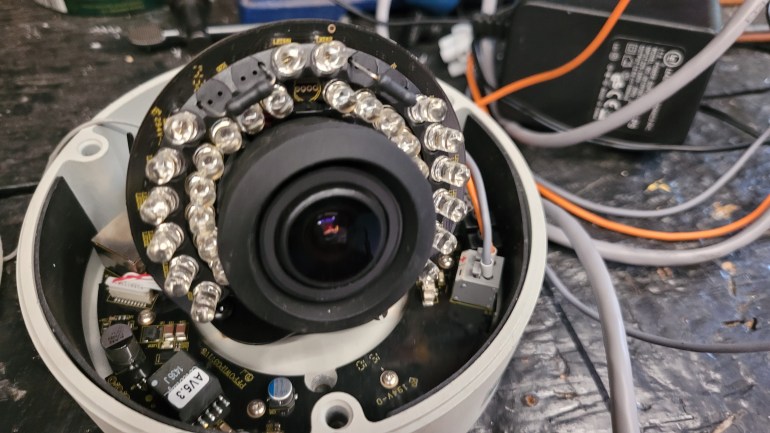
Compared to security cameras from nowadays this doesn’t seem to be very impressive, but remember this unit got introduced in a moment in time where CMOS sensors where just being picked up. The camera is no longer working correctly so let’s further dismantle it.

With the dome opened up we get a much better glimpse of what the internals looks like. So we have the camera lens surrounded by IR LEDs to help the camera capture night scenes. All together this sits on a mechanical structure that allows you to manually rotate the camera over all axis. The security camera however does not feature any motors so we can’t move or rotate the field-of-view electronically through PTZ controls.

The bottom of the dome has a second PCB that connects to the stacked camera PCBs via various cables. The goals of the bottom PCB is to offer various connections and contacts for external wiring. It’s does not contain any computational chips, so it’s rather some sort of IO board.

Available are ethernet and 12V DC power, but also alarm contacts, audio out, analog video out and RS485.

The complete bottom PCB. Notice the various small wires coming from the bottom PCB , and going through the mechanical manual pan/tilt structure.

Let’s focus again on the camera parts itself. It is made out of various PCBs stacked together:

It’s very typical for IP cameras because there is only very little space to pack a lot of functionality. We start with the most outer PCB, the closest one to the bottom PCB. It contains an SD-card interface for data storage purposes (maybe it can also update the camera?), but there is also a debug connector available at the left side of the picture. Unfortunately it has 5 pins, which is less common, and I didn’t wanted to trace the wiring of it.

The big MS1601SP is a Single Channel Interface For 10/100Mbps Ethernet.

Back view on the PCB:

From here one we continue to the middle PCB which contains some logic ICs:

One of the most profound chips is the Texas Instruments DM365, which is a DaVinci Digital Media Processor. This chip is a slow speed sort of DSP that takes the camera sensor’s raw image data and turns it into 720P H264 media streams. It’s build around a ARM926EJ-S RISC processor running at about 300MHz. It contains the MMC/SD card interface, as well as ethernet, audio, GPIO, USB2, a DDR2 memory controller and a NAND storage memory interface. The capture pipeline contains an ISP and hardware 3A (Auto Focus (AF) engine, Auto Exposure (AE), Auto White Balance (AWB) engine) implementation, and is also capable of hardware facial detection. To connect to an image sensor the ISIF (Image Sensor Interface Format) interface is used which supports both CMOS and CCD sensors. Remember, this camera was being developed when MIPI-CSI was only starting to finds it ways into embedded chips, so hence it’s not yet supported in this chip.

The chip that sits at the lefts side of the TI SOC is a DDR2 memory chip of which I couldn’t find the datasheet. On the right side we have a Davicom DM9161B 10/100 Mbps Fast Ethernet Physical Layer Single Chip Transceiver.

And on the back, we easily spot the EON EN27LN1G08 NAND Flash chip. It’s a 3V3 chip containing a 128 x 8 memory array, good for 1 Gigabit of storage.

From the middle PCB we have a big flat cable that connects to a third PCB: the camera sensor board. While not easy to say, this is a 1/3” Sony 1.3 Megapixel Progressive Exmor™ CMOS Sensor.

The camera sensor has mounted a decently large lens with manual focus.

The sensor is also surrounded by another PCB which contains all the IR LEDs.

This PCB is rather simplistic in that it mostly contains the LEDs, some FP702 amplifiers, and 4 wire cable connector to control the LEDs.

Also notice the 2 clumsy resistors. It could actually well be that those are big for a reason, for example for dew control.

This IP camera is aged, no longer working at this point and some of the chips dating from 15y back. We could probable try to boot our own linux on it, or at least try to figure out how the debug port. works But truth is that it’s actually to old to really grasp my interest beyond this point as the camera its internals have grown largely incompatible with todays standards. It’s nice to see the complexity of building IP cameras and how they solved it already 15y back from now. The TI Davinci Media SOC was something I didn’t know yet so that was definitely something worthy to learn about. And I was also surprised to see how they already got facial detection prior to the machine learning capable systems that we have nowadays.

LittlevGL port for mbed-os

With the Corona COVID-19 virus among us I’ve moved my development setup from work to my place at home. My working hours have also been cut roughly in half which leaves some time to experiment with the hardware I normally only have available at work. One of our development devices features a STM32 F429 chip, SSD1309 OLED, and some sensors. All together its a very good candidate to run some custom demo’s that I’ve been willing to try for some time now.

I’m already aware LittlevGL for some time now, but since we don’t have any project running which requires a GUI library I never l looked any further into the matter. Last summer I saw a demo of Qt on MCU and I was astonished by the outcome of it. It looked very good but unfortunately also requires quite a beefy MCU. Fast forward to the beginning of this year. The Elector magazine had an interview with LittvGL author Gábor Kiss which certainly brought up some sympathy and respect for what this guy (and the many contributors) have been building lately.

So, wanted something on my hands and started looking into the matter. I was pleased to find that LittlevGL has already been ported to the mbed-os that I’m targeting. Furthermore I also found some other blog posts such as “Porting LittlevGL for a monochrome display” and “LittlevGL on a Monochrome OLED” to further guide me to get the bits working.

The target display is a monochrome 128×64 pixels OLED which is a far cry from the many other popular embedded displays. Anyhow, LittlevGL has a monochrome theme so it shouldn’t stop you from using it. Here is the result:

IMG_20200403_151739402-COLLAGE.jpg

The hardest part of making your port work is grasping how to translate LittlevGL’s inner working to your display driver. For example, LittlevGL draws/updates only part of the screen that has changed. It can also work with a framebuffer that’s smaller than your actual display size. Once you understand such features and when you figured out how to drive your display, writing the LittlevGL implementation isn’t too hard. LittlevGL has decent documentation and is much lower on resources compared to Qt’s counterpart. I can definitely recommend it for any if your MCU projects that require a GUI. It’s also very fast and which resulted in very smooth animations.

Running Doom on a i.MX6 with Yocto Linux

Although I’ve missed most of the hype around the original Doom game back in the 90’s, I did get to play it at a friends place. But it was only until I started programming that I picked it up again after reading Master’s of Doom.

When I started working on a embedded Linux device last year based on the i.MX6 processor the idea began to grow to compile Doom for our custom Linux based OS as some sort of easter egg. Unfortunately the world is real and deadlines are always too short and I had to let go of this idea. More recently however some of our dev-boards had to be archived and so I took this opportunity to take one home for a short period of time and finally get this one settled for once and for all.

One way to get it working is to setup a cross-compilation toolchain and cross-compile one of the many source ports of the doom engine. Another way would be to properly integrate it with the build of our custom Linux OS. Since we’re using Yocto to build our image the idea was to create a separate meta-layer that includes everything you need. You can find the meta-layer at github/geoffrey-vl/meta-doom.

Initially I started integrating the prboom engine. I found out that the out-of-three build  wasn’t working so well and I’ve bumped into some other issues’s as well. I had more luck using chocolate-doom which is better maintained. Chocolate-doom only recently switched over to using the SDL2 library so to be on the safe side I went to the latest version that runs on SDL(1). The game engine also requires libsdl-net which is currently not available in the official yocto repo’s. Luck was on my side when I bumped into a working libsdl-net recipe through google-search.

With the engine compiling happily I stumbled upon licensing issues. You have to own the game (and its game aka WAD files), so I couldn’t distribute anything that would be playable unless the user would copy its WAD files to our embedded system. Luckily there is the Freedoom project, a open-source implementation of the doom game. I also found a working recipe for Freedoom and so moments later my workstation produced a ready-to-play open-source implementation of the immensely populair Doom game.

Just for the kicks I also loaded my own WAD files, here is the result:


Logging temperature using an Arduino and AD7410 sensor

This article is a quick and dirty demonstration to hack yourself a temperature data logger which saves its results to an SD card. The sensor of use is a HTU21D, a I²C temperature and humidity sensor.

hookup

Schematic:

hookup_bb

I hooked up a HTU21D sensor to an Arduino Uno + SD-card shield and let it monitor temperature (and humidity) over an entire day:

24h_log

Here is a close-up of what happens at night:

3h_log

Source code:

/*
 SD card datalogger

This example shows how to log data from three analog sensors
 to an SD card using the SD library.

The circuit:
 * analog sensors on analog ins 0, 1, and 2
 * SD card attached to SPI bus as follows:
 ** MOSI - pin 11
 ** MISO - pin 12
 ** CLK - pin 13
 ** CS - pin 4

created 24 Nov 2010
 modified 9 Apr 2012
 by Tom Igoe

This example code is in the public domain.

*/
 /*
 HTU21D Humidity Sensor Example Code
 By: Nathan Seidle
 SparkFun Electronics
 Date: September 15th, 2013
 License: This code is public domain but you buy me a beer if you use this and we meet someday (Beerware license).

 Uses the HTU21D library to display the current humidity and temperature

 Open serial monitor at 9600 baud to see readings. Errors 998 if not sensor is detected. Error 999 if CRC is bad.

 Hardware Connections (Breakoutboard to Arduino):
 -VCC = 3.3V
 -GND = GND
 -SDA = A4 (use inline 330 ohm resistor if your board is 5V)
 -SCL = A5 (use inline 330 ohm resistor if your board is 5V)

*/

#include <SPI.h>
#include <SD.h>
#include <Wire.h>
#include "SparkFunHTU21D.h"

//Create an instance of the object
HTU21D myHumidity;

const int chipSelect = 4;

// make a string for assembling the data to log:
String dataString = "";

void setup() {
 // Open serial communications and wait for port to open:
 Serial.begin(9600);
 while (!Serial) {
 ; // wait for serial port to connect. Needed for native USB port only
 }

 myHumidity.begin();
 Serial.println("HTU21D ready!");

Serial.print("Initializing SD card...");

// see if the card is present and can be initialized:
 if (!SD.begin(chipSelect)) {
 Serial.println("Card failed, or not present");
 // don't do anything more:
 return;
 }
 Serial.println("card initialized.");
}

void loop() {
 readTemp();

Serial.println("Writing data...");
 // open the file. note that only one file can be open at a time,
 // so you have to close this one before opening another.
 File dataFile = SD.open("datalog.txt", FILE_WRITE);

// if the file is available, write to it:
 if (dataFile) {
 dataFile.println(dataString);
 dataFile.close();
 // print to the serial port too:
 Serial.println(dataString);
 }
 // if the file isn't open, pop up an error:
 else {
 Serial.println("error opening datalog.txt");
 }
 delay(10000);
}

void readTemp() {
 float humd = myHumidity.readHumidity();
 float temp = myHumidity.readTemperature();

 // make a string for assembling the data to log:
 dataString = "Time: ";
 dataString += String(millis());
 dataString += String("; Temperature: ");
 dataString += String(temp);
 dataString += String("; Humidity: ");
 dataString += String(humd);
 dataString += String("%");
}

This was just a quick and dirty hack to get some instant results. I’m planing to do some more logging in the future to get a better understanding of how to approach my self build climate control. Stay tuned for more.

BIOS bypassing, yet again

Well, not so long ago I had to bypass a BIOS password on a government computer. Some google wizardness quickly revealed a lot of laptops actually have some kind of admin/master password which can reverse engineered or brute forced, any way you want. I already told you about the http://bios-pw.org/ website which could help you for a great deal. If not, maybe Dogbert’s Blog is something for you. He has some nice tools for you to download, including the source code. Great job man!

Dell E4300 BIOS hacking

I just got my hands on a 2nd hand Dell Latitude E4300 laptop previously owned by the Belgian Ministry of Justice. The computer has a functional Windows license on it, however the computer is currently configured in a Administrative Domain so any normal users that could possible log into this machine is not allowed to install any software. Furthermore, since I didn’t have any user credentials I was forced to find a way to bypass the AD user login. Linux  gives us some possibilities, however since the BIOS is locked by a administrative password I was not able to select or change any other boot device aside of the hard drive. One solution is to unscrew the hard drive and install it into another computer where you do have the boot options available. However, bypassing the BIOS admin password is not so hard either on these machines and requires just some googling…

To get into the administrative password protected BIOS, first press f12 during system boot to get into the E4300 BIOS. You’ll notice the unlock button at the bottom. Press it and you’ll be asked for the admin password. You can however obtain the master password from the following website: http://bios-pw.org/, enter your serial number (might look like this: 1234567-2A7B), and use the password that is given by “Dell by serial number”. So in the BIOS, press the unlock button, next enter the password and press ctrl + enter and now you should get into the unlocked BIOS. One remark here: the password should be entered on a QWERTY keyboard, for AZERTY keyboards you’ll have to convert your password to a QWERTY string. So, if for example you get the following response from the BIOS-PS.ORG website: “Dell by serial number: hTfn7Xz3yWqg8”, then you should enter “hTfnèXw”yZag!” on a Belgian AZERTY keyboard. So the trick here is to enter numbers without using the shift button as you’re used to, switch “q” with “a”, “z” with “w”, and “m” with “,”.

Now, make yourself a LINUX life boot cd, mount the windows drive and save whatever data you wanted to safe. Good luck!